As discussed in the "Protected Ports (PVLAN Edge") section, the PVLAN feature prevents interhost communications providing port-based security among adjacent ports within a VLAN across one or more switches. PVLAN provides Layer 2 isolation to quarantine hosts from one another among ports within the same PVLAN.
Access ports in a PVLAN are allowed to communicate only with the certain designated router ports. In most cases, this is the default gateway IP address. Private VLANs and normal VLANs can coexist on the same switch. The PVLAN feature allows segregating traffic at Layer 2, thereby transforming a broadcast segment into a nonbroadcast multi-access-like segment. To prevent interhost and interserver communication, PVLAN can be used efficiently because the number of subnets or VLANs is greatly reduced, although the segmented approach within a single network segment is still achieved. The number is reduced because there is no need to create extra subnet/VLANs.
Note
The PVLAN feature is not available on all Cisco switches. Refer to Table 4-1 for a list of supported platforms.
| Platform | Software Version | Isolated VLAN | PVLAN Edge (Protected Port) | Community VLAN |
|---|---|---|---|---|
| Catalyst 8500 | Not Supported | — | — | — |
| Catalyst 6500/6000—CatOS on Supervisor and Cisco IOS on MSFC | 5.4(1) on Supervisor and 12.0(7)XE1 on MSFC | Yes | N/A | Yes |
| Catalyst 6500/6000—Cisco IOS System software | 12.1(8a)EX, 12.1(11b)E1 | Yes | N/A | Yes |
| Catalyst 5500/5000 | Not Supported | — | — | — |
| Catalyst 4500/4000—CatOS | 6.2(1) | Yes | N/A | Yes |
| Catalyst 4500/4000—Cisco IOS | 12.1(8a)EW | Yes | N/A | 12.2(20)EW |
| Catalyst 3750 | 12.2(20)SE—EMI | Yes | 12.1(11)AX | Yes |
| Catalyst 3750 Metro | 12.1(14)AX | No | Yes | No |
| Catalyst 3560 | 12.2(20)SE—EMI | Yes | 12.1(19)EA1 | Yes |
| Catalyst 3550 | 12.1(4)EA1 | No | Yes | Not Currently Supported |
| Catalyst 2970 | 12.1(11)AX | No | Yes | No |
| Catalyst 2955 | 12.1(6)EA2 | No | Yes | No |
| Catalyst 2950 | 12.0(5.2)WC1, 12.1(4)EA1 | No | Yes | Not Currently Supported |
| Catalyst 2900XL/3500XL | 12.0(5)XU (on 8MB switches only) | No | Yes | No |
| Catalyst 2948G-L3 / 4908G-L3 | Not Supported | — | — | — |
| Catalyst 2948G/2980G | 6.2 | Yes | N/A | Yes |
| Catalyst 2940 | 12.1(13)AY | No | Yes | No |
| Catalyst 1900 | Not Supported | — | — | — |
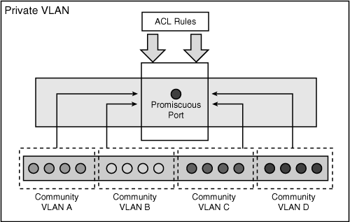
The list that follows describes three types of PVLAN ports, as shown in Figure 4-1a:
Promiscuous: A promiscuous port can communicate with all interfaces, including the isolated and community ports within a PVLAN. The function of the promiscuous port is to move traffic between ports in community or isolated VLANs. It can use access lists to identify which traffic can pass between these VLANs. Only one promiscuous port is allowed per single PVLAN, and it serves all the community and isolated VLANs in the Private VLAN.
Isolated: An isolated PVLAN port has complete Layer 2 segregation from all the other ports within the same PVLAN, but not from the promiscuous ports. Traffic from the isolated port is forwarded only to the promiscuous ports and none other.
Community: Community ports are logically combined groups of ports in a common community and can pass traffic among themselves and with promiscuous ports. Ports are separated at Layer 2 from all other interfaces in other communities or isolated ports within their PVLAN.

It is possible for isolated and community port traffic to enter or leave the switch through a trunk interface because trunks support VLANs carrying traffic among isolated, community, and promiscuous ports. Hence, PVLAN ports are associated with a separate set of VLANs that are used to create the PVLAN structure. A PVLAN uses VLANs in following three ways:
As a primary VLAN: Carries traffic from a promiscuous port to isolated, community, and other promiscuous ports in the same primary VLAN.
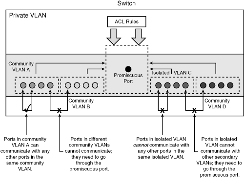
As an isolated VLAN: Carries traffic from isolated ports to a promiscuous port. Ports in the isolated VLAN cannot communicate at Layer 2 with any other port within the Private VLAN (either another community VLAN port or a port in the same isolated VLAN). To communicate with other ports, it must go through the promiscuous port.
As a community VLAN: Carries traffic between community ports within the same community VLAN and to promiscuous ports. Ports in the community VLAN can communicate at Layer 2 with each other (only within the same community VLAN) but cannot communicate with ports in other community or isolated VLANs. To communicate with other ports, they must go through the promiscuous port. Multiple community VLANs can be configured in a PVLAN.
Figure 4-1a depicts the basic PVLAN components and the different types of PVLAN ports.
The isolated and community VLANs are also called secondary VLANs. PVLANs can be extended across multiple devices by trunking the primary, isolated, and community VLANs to other devices that support PVLANs.
In summary, a Private VLAN contains three elements: the Private VLAN itself, the secondary VLANs (known as the community VLAN and isolated VLAN), and the promiscuous port.
Figure 4-1b summarizes the PVLAN components and traffic flow policies among the PVLAN ports.

Table 4-1 shows a list of Cisco switches that support the PVLAN feature with the respective software version.
Note
When enabling PVLAN, it is important to remember to configure the switch as VTP transparent mode before you can create a PVLAN. PVLANs are configured in the context of a single switch and cannot have members on other switches.
Perform the following steps to configure the PVLAN feature:
Use the show interface private-vlan mapping command and the show interface [interface-id] switchport command to verify the configuration.
When a packet arrives at the switch, the switch performs a lookup for the destination MAC address in the MAC address table to determine which port it will use to send the packet out to send on. If no entry is found in the MAC address table, the switch will broadcast (flood) unknown unicast or multicast traffic out to all the ports in the same VLAN (broadcast domain). Forwarding an unknown unicast or multicast traffic to a protected port could raise security issues.
Unknown unicast or multicast traffic can be blocked from being forwarded by using the port blocking feature.
To configure port blocking for unknown unicast and multicast flooding, use the following procedures:
By default, ports are not configured in blocking mode. Example 4-2 shows how to enable and verify switch ports configured for the port blocking feature.
Switch(config)# interface Fastethernet0/1 Switch(config-if)# switchport block multicast Switch(config-if)# switchport block unicast Switch(config-if)# end Switch# show interfaces FastEthernet 0/1 switchport Name: Fa0/1 Switchport: Enabled Administrative Mode: static access ... Protected: true Unknown unicast blocked: enabled Unknown multicast blocked: enabled Appliance trust: none |
Port security is a dynamic feature that prevents unauthorized access to a switch port. The port security feature can be used to restrict input to an interface by identifying and limiting the MAC addresses of the hosts that are allowed to access the port. When secure MAC addresses are assigned to a secure port, the switch does not forward packets with source MAC addresses outside the defined group of addresses. To understand this process, think of the analogy of a secure car park facility, where a spot is reserved and marked with a particular car registration number so that no other car is allowed to park at that spot. Similarly, a switch port is configured with the secure MAC address of a host, and no other host can connect to that port with any other MAC address.
Port security can be implemented in the following three ways:
Static secure MAC addresses are manually configured using the switchport port-security mac-address [source-mac-address] command and stored in the MAC address table and in the configuration.
Dynamic secure MAC addresses are dynamically learned, stored in the MAC address table, but removed when the switch is reloaded or powered down.
Sticky secure MAC addresses are the combination of items 1 and 2 in this list. They can be learned dynamically or configured statically and are stored in the MAC address table and in the configuration. When the switch reloads, the interface does not need to dynamically discover the MAC addresses if they are saved in the configuration file.
In the event of a violation, an action is required. A violation occurs when an attempt is made to access the switch port by a host address that is not found in the MAC address table, or when an address learned or defined on one secure interface is discovered on another secure interface in the same VLAN.
An interface can be configured for one of the following three security violation modes, based on the action to be taken when a violation occurs:
Protect: This puts the port into the protected port mode, where all unicast or multicast packets with unknown source MAC addresses are dropped. No notification is sent out in this mode when security violation occurs.
Restrict: Packets with unknown source addresses are dropped when the number of secure MAC addresses reaches the set limit allowed on the port. This continues until a sufficient number of secure MAC addresses is removed or the number of maximum allowable addresses is increased. Notification is sent out in this mode that a security violation has occurred. An SNMP trap is sent, a syslog message is logged, and the violation counter is incremented.
Shutdown: When a port security violation occurs, the port is placed in error-disabled state, turning off its port LED. In this mode, an SNMP trap is sent out, a syslog message is logged, and the violation counter is incremented.
To enable the port security feature, use the switchport port-security interface configuration command. The command has several options.
Example 4-3 shows how to configure a static secure MAC address on a port and enable sticky learning.
Switch(config)# interface Fastethernet0/1 Switch(config-if)# switchport mode access Switch(config-if)# switchport port-security Switch(config-if)# switchport port-security mac-address 0009.6B90.F4FE Switch(config-if)# switchport port-security mac-address sticky Switch(config-if)# end |
Example 4-4 shows how to configure a maximum of 10 secure MAC addresses on VLAN 5 on port interface FastEthernet 0/2. The [vlan] option in this command sets a maximum value per VLAN for the specified VLAN or range of VLANs.
Switch(config)# interface Fastethernet0/2 Switch(config-if)# switchport mode access Switch(config-if)# switchport port-security maximum 10 vlan 5 Switch(config-if)# end |
In addition to the configuration shown in Example 4-4, a port-security aging mechanism can be configured. By default the secure MAC addresses will not be aged out, and in normal port security configuration, the entries will remain in the MAC table until the switch is powered off. When using the sticky option, these MAC addresses will be stored until cleared manually.
There are two types of aging mechanisms:
Absolute: The secure addresses on the port age out after a fixed specified time, and all references are flushed from the secure address list.
Inactivity: Also known as idle time, the secure addresses on the port age out if they are idle, and no traffic from the secure source addresses passes for the specified time period.
Example 4-5 shows how to configure the aging time to 5 minutes for the inactivity aging type. In this example, aging is enabled for statically configured secure addresses on the port.
Switch(config)# interface Fastethernet0/1 Switch(config-if)# switchport mode access Switch(config-if)# switchport port-security aging time 5 Switch(config-if)# switchport port-security aging type inactivity Switch(config-if)# switchport port-security aging static |