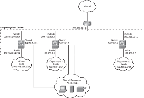
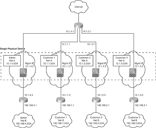
Software Version 7.0 introduced the capability to create multiple virtual firewalls, which are also referred to as security contexts within a single appliance. Multiple contexts are similar to having multiple standalone devices. Each virtualized partition is an independent device and has its own set of security policies (NAT, access list, routing, and so on), logical interfaces, and administrative domain. Multiple contexts mode supports almost all the options that are configurable on a standalone device, such as NAT, firewall features, routing tables, IPS, and management features. Some features, such as VPN and dynamic routing protocols, are not supported in multiple context mode. In addition, interfaces can be shared between contexts but supported in routed mode only. For example, the outside interface can be shared to conserve interfaces, or Inside and demilitarized zone (DMZ) interfaces can be used to share resources between contexts.
There are a number of ways to set up a Security Appliance in multiple mode. The following sections illustrate two common ways for the implementation, including sharing an interface between the contexts.
Figure 6-6 shows an admin context plus two multiple contexts for multiple departments within an organization, each with three segments: an Inside, an Outside, and a shared segment. Each department has its own security context (virtual firewall) so that it can have its own security policy (NAT, access list, routing, and so on). Several servers are shared across both departments. Hence these servers are placed on a shared network using the shared interface concept.

Figure 6-7 shows an admin context plus three multiple contexts for multiple customers in a transparent mode. Each customer has its own security context with its own security policy (NAT, access list, static routes, and so on). A transparent firewall is in a secure bridging mode and connects the inside and outside interfaces to the same network (Net A). Each security context is assigned a management IP address of 10.1.x.2 on the same connected (Net A) IP subnet.

Note
In multiple mode environments, all contexts can be configured either in routed or transparent mode. Mix-mode environment is not supported.
Caution
Dynamic routing protocols are not supported in multiple context modes; static routing can be used. VPN and Multicast are also not supported.
How does the Security Appliance classify which context to send a packet to?
All packets entering the appliance must be classified to determine which context to send a packet to. The classifier uses the following policy to assign the packet to a context:
Unique Interface: If only one context is associated with the ingress interface, the Security Appliance classifies the packet into that context. Note that when using the transparent mode, use unique interfaces only because transparent mode requires unique interface allocation for each context. For routed mode, the following methods also apply.
Unique MAC Address: If multiple contexts are associated with the ingress interface, the appliance classifies the packet into a context by matching interface MAC addresses. By default, shared interfaces in a context do not have a unique MAC address, and it uses the default physical MAC address in every context. This can cause ARP issues as an upstream device cannot send the packet to the correct context due to the duplicate MAC address across multiple context interfaces. The solution is to assign a unique MAC address to the shared interface within each context. This can be done using the mac-address mac_address [standby mac_address] command under the interface configuration mode. Alternatively, you can use the global command mac-address auto to automatically generate MAC addresses to each shared context interface.
Address Translation: If you are not using unique MAC addresses as just explained, then Security Appliance classifies the packet into a context by matching the destination address to one of the following context configurations. The classifier relies on the NAT configuration and matches the destination IP address in either a static command or global command and looks at the following:
To define a context mode, add, or change a context in the system configuration, perform the following steps:
Step 1. | Define the context mode (single or multiple). Use the mode {single | multiple} command from the global configuration. The appliance will require a reboot. Note that the mode configuration is not stored in the configuration file. |
Step 2. | To add or modify a context in the system execution space or the admin context, use the context {name} command from the global configuration mode to enter the context submode. The prompt changes to the following to indicate it is still in the system execution space and is modifying parameters for the specific context: hostname(config-ctx)# |
Step 3. | Specify the interface(s) allocated to a context. Enter the command appropriate for a physical interface or for one or more subinterfaces using the allocate-interface command from the context submode. Repeat these commands multiple times to specify different ranges. Note that the transparent firewall mode allows for only two interfaces to pass through traffic. Same interfaces can be assigned to multiple contexts in routed mode, if desired. Transparent mode does not allow shared interfaces. |
Step 4. | Identify the URL from which the system downloads the context configuration by using the config-url command. Context configuration can be downloaded via several methods, such as internal flash, HTTP/HTTPS, TFTP, or using FTP server. |
Step 5. | Change between contexts to perform configuration and monitoring tasks within each context by using the changeto context {name} command. The prompt changes to the following: hostname/context-name# |
Step 6. | To view the context information, use the show context [name | detail| count] command. |
Example 6-1 shows how to enable multiple contexts mode. The example sets the admin-context to be administrator, creates a context called "administrator" on the internal flash memory, and adds another two contexts: a context called customerA from an FTP server, and another context called customerB from internal flash. Note that the context names are case sensitive.
|
Code View: hostname(config)# mode multiple hostname(config)# admin-context administrator hostname(config)# context administrator hostname(config-ctx)# allocate-interface Ethernet0.1 hostname(config-ctx)# allocate-interface Ethernet1.1 hostname(config-ctx)# allocate-interface Management0/0 hostname(config-ctx)# config-url flash:/admin.cfg hostname(config-ctx)# context customerA hostname(config-ctx)# allocate-interface Ethernet0.100 int1 hostname(config-ctx)# allocate-interface Ethernet0.102 int2 hostname(config-ctx)# allocate-interface Ethernet0.103-Ethernet0.108 int3-int8 hostname(config-ctx)# config-url ftp://joe:password@10.1.1.1/configs/ customerA.cfg hostname(config-ctx)# context customerB hostname(config-ctx)# allocate-interface Ethernet1.200 int1 hostname(config-ctx)# allocate-interface Ethernet1.202-Ethernet1.203 int2-int3 hostname(config-ctx)# allocate-interface Ethernet1.205-Ethernet1.210 int5-int10 hostname(config-ctx)# config-url flash:/customerB.cfg |
Example 6-2 shows how to change between contexts and the system execution space in privileged EXEC mode to perform configuration and monitoring tasks within each context. The system execution space is the admin context from where you can switch between the contexts. Ensure the location, because the configuration changes made are applicable to the current position (within the context). For example, when the show running-config command is executed, it will display only the current configuration of that context and not the running configurations of all contexts (system plus all contexts).
hostname/admin# changeto system hostname# changeto context customerA hostname/customerA# OR hostname# changeto context customerB hostname/customerB# |