To achieve a high degree of availability and load-sharing capability, devices in the network must facilitate a redundancy feature and a mechanism to establish a failure and speedy recovery process. The Security Appliance offers features that increase availability and load-sharing ability to offer a fault-tolerant solution that ensures maximum uptime and maximized resource utilization. Redundancy is one of the key elements in building robust networks.
The Security Appliance offers a failover function that provides a safeguard mechanism in the event of a unit failure. When one unit fails, another immediately takes its place. The Security Appliance supports the following two types of failover setup. Both failover modes support stateful or stateless failover.
Active/Standby Failover Mode (Redundancy): In this mode, only one unit (the primary, also called the Active unit) passes traffic, whereas the other unit is in a standby state. The Active/Standby failover is available in both single and multiple context modes.
Active/Active Failover Mode (Load Balancing): In this mode, both devices can pass network traffic by sharing bandwidth resources on both devices. The Active/Active mode provides high-resilience, high-availability networks with load-balancing capability. The Active/Active failover mode is available on multiple contexts mode only.
Both Security Appliances in a failover pair must be identical to each other and connected through a dedicated failover link (interface) and optionally, a state link interface. To enable the failover feature on the Security Appliance, the criteria that follows must be met. (Note that both units must have the same hardware and software configuration.) In the list that follows, both units must
Be the same model
Have the same number and types of interfaces
Have the same amount of Flash memory and the same amount of RAM
Be in the same operating mode (routed or transparent, single or multiple context)
Have same major (first number) and minor (second number) software version; for example, with version 8.0(3), the number 3, which is in the parenthesis, can vary between the two devices, but 8.0 must be the same
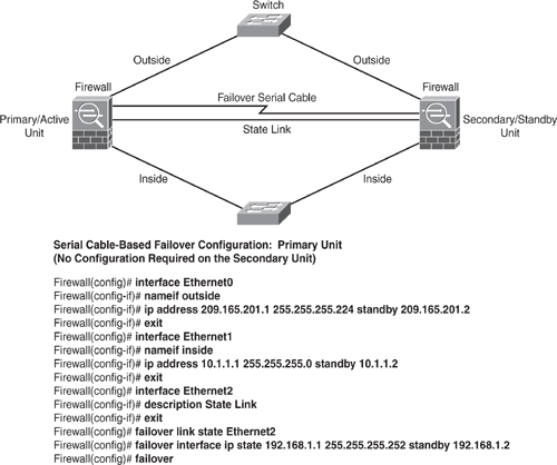
The failover link interface is used to monitor the health and operating status of each unit in a failover mode. On the PIX 500 series platform, the failover link can be either a LAN-based connection or a dedicated serial failover cable. On the ASA 5500 series platform, the failover link can only be a LAN-based connection.
The Security Appliance supports two types of failover, regular and stateful. In a regular failover mode (nonstateful), all active connections are dropped, and clients need to reestablish connections when the new active unit takes over, because the new active device has no knowledge of the previous connections. In a stateful-failover environment, active connections do not need to reestablish when a failover occurs. For example, if the client has an active connection that is transferring a file via FTP protocol, when the fail occurs, the file copying continues uninterrupted via the standby unit that has assumed an active role.
The state link interface is used to pass the state of all established connections from the active unit to the standby device. The information that is passed to the standby unit in a stateful failover setup includes the following:
NAT translation table
TCP connection states
UDP connection states
The ARP entries
The Layer 2 bridge table when running in transparent firewall mode
The HTTP connection states (if HTTP replication is enabled)
The Internet Security Association and Key Management Protocol (ISAKMP) and IPsec SA table
The connection database for GPRS Tunneling Protocol (GTP) Packet Data Protocol (PDP)
The exception to information that is not passed to the standby unit in a stateful failover setup is the following:
The HTTP connection table (unless HTTP replication is enabled)
The user authentication (uauth) table
The routing tables
Multicast traffic information
State information for Security Service Cards
There are three options for configuring a state link when configuring failover:
1. | Use any unused Ethernet interface on the Security Appliance as a dedicated state link. |
2. | When using LAN-based failover, use the failover link for a state link (same Ethernet for dual purpose). |
3. | Use the regular data Ethernet interface for the state link; however, this is not a recommended practice, although supported. |
The state link interface is not configured as a normal networking interface for normal operations; it exists only for stateful failover communications and, optionally, for the failover communication when the state and failover links are shared. Connect the state link by using a dedicated hub/switch, or segment it with a VLAN with no hosts or devices on the link or by using a crossover Ethernet cable to link the units directly.
The failover implementation on the Security Appliance can be deployed in two options: the Serial Cable Failover link or LAN-based failover link modes.
The serial Failover cable, or cable-based failover, is available only on the PIX 500 series platform. This design is recommended for use when the two PIX units are within six feet of each other. The main advantage of using this type of cable is that it is a dedicated serial cable, which provides faster convergence. The Security Appliance can sense a power loss of the peer unit and quickly differentiate a power loss from an unplugged cable. The main drawback in this type is the distance limitation (the units cannot be separated by more than six feet). The cable that connects the two units is a six-foot modified RS-232 serial cable that transfers data at 117,760 bps (115 Kbps). One end of the cable is labeled "Primary" and is attached to the primary unit, whereas the other end is labeled "Secondary" and is attached to the secondary unit. Figure 6-20 shows a configuration example.

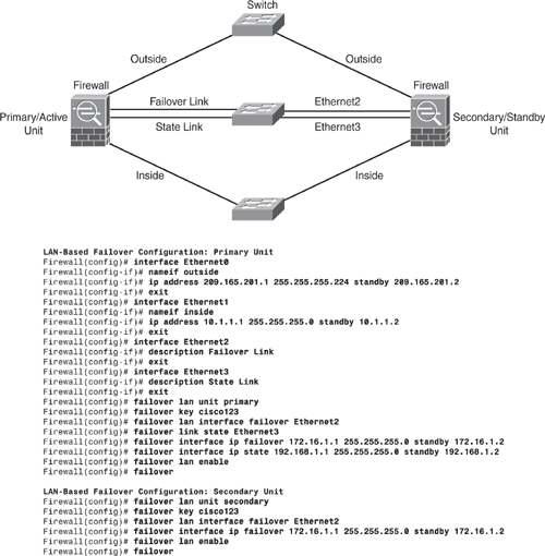
Unlike the serial-cable failover implementation, the advantage of using LAN-based failover is the physical distance of the units, which can be more than six feet, and the faster configuration replication. The downside is slower convergence; the Security Appliance cannot immediately detect the loss of power of a peer, hence the firewall takes longer to failover in this case.
To replace the serial cable from the previous method, the LAN-based failover link uses the Ethernet interface on the appliance for failover link. This interface can also be used for normal network operation and can be optionally used for the state link. The failover link should be connected either via a dedicated switch or by putting in a VLAN with no other hosts/devices, or by connecting it using a crossover Ethernet cable. In multiple context mode, the failover link needs to be on the system context (admin context). Figure 6-21 shows a configuration example.

Note
Refer to Cisco documentation for additional failover configuration examples, such as LAN-based Active/Active: http://www.cisco.com/en/US/products/ps6120/products_configuration_guide_chapter09186a008045247e.html#wp1046980.
The Active/Active mode additionally provisions the ASR (Asymmetric Routing Support) feature. The ASR technology allows the unit to forward the received packet for which it does not have an active connection by looking for a corresponding connection on the other interfaces in the asynchronous routing group. In regular firewall mode, if the connection originates through one device, and the ISP routes the return traffic through another device, the packet is dropped. ASR prevents the return packets from being dropped in such environments. With the ASR feature, the connection information is forwarded to the secondary pair unit, and it will forward the traffic to the unit that holds the connection information.