The switch includes a switching processor (called the supervisor) and a router (called the MSFC–Multilayer Switch Feature Card). MSFC provides Cisco IOS-based multiprotocol routing and network services. It is important to understand the logical placement of the Router/MSFC in the network topology in relation to the FWSM. Several criteria are outlined in the subsections that follow that can be used to determine the network flow between the networks that require firewalling functions. The sections that follow explain the scenarios that are used to place the Router/MSFC in single and multiple contexts.
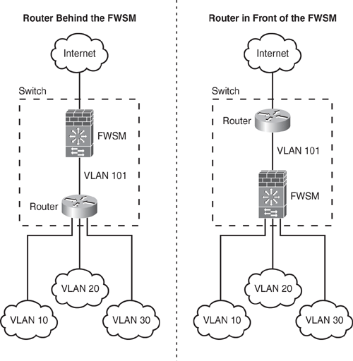
In single context mode, the Router/MSFC can be placed either in front of the firewall or behind the firewall, as shown in Figure 6-22. The placement of the Router/MSFC depends entirely on the logic and requirement of the network flow—for example, determining which VLANs require being pushed through the firewall for inspection and/or need to bypass the firewall. If Router/MSFC is performing inter-VLAN routing between the VLANs, the firewall is not going to see that traffic.

For example, in Figure 6-22, the Router is placed behind the firewall on the left, routing packets among VLANs 10, 20, 30, and 101. In addition, inter-VLAN traffic does not go through the FWSM unless traffic is destined for the Internet. Hence, traffic flow among VLANs (inter-VLAN) is not protected. On the right-side example of Figure 6-22, the router is placed in front of the firewall, and the switch is configured to push VLANs 10, 20, and 30 traffic to the FWSM, thereby protecting all traffic among these VLANs (inter-VLAN) and traffic going to the Internet.
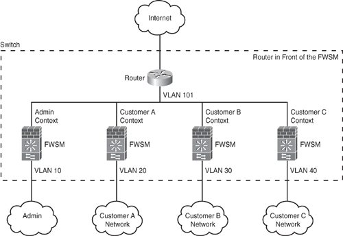
In multiple context mode, the recommended placement for the router is in front of all the contexts to route traffic among the Internet and switched networks, as shown in Figure 6-23. Placing the router behind the FWSM results in routing among the multiple contexts, which forfeits the concept of multiple context and segment isolation.
