The Security Appliance runs in two firewall modes:
In this mode, the Security Appliance is considered to be a router hop in the network. (This is the regular mode that everyone is familiar with.) Network Address Translation and dynamic routing protocol capabilities using Routing Information Protocol (RIP) and Open Short Path First (OSPF) can be performed in this mode. Note that routing protocols RIP and OSPF are supported in single context mode only. Multimode context does not support routing. In addition, routed mode supports use of multiple interfaces. Each interface must be on a different subnet, and interfaces can be shared between contexts. By default, routed mode is set as the default mode.
Firewall Software Version 7.0 and later introduces the capability to deploy the Security Appliance in a secure bridging mode, as a Layer 2 device, to provide rich Layer 2 through 7 firewall services. In a transparent mode, the Security Appliance acts like a "bump in the wire" and is not a router hop. There is no need to redesign the IP network (Layer 3 addressing scheme). The Security Appliance connects the same network (IP subnet) on its inside and outside interfaces. The inside and outside interfaces are put on different Layer 2 segments if they are connected on the same switch (use unique VLAN numbers or use separate switches).
In essence, the network is split into two Layer 2 segments and the appliance is placed in between, thereby acting in bridge mode, and Layer 3 remains unchanged. Alternatively, clients can be connected on either side into two separate switches that are independent of each other (and not connected to each other in any way).
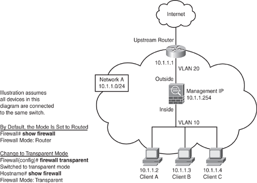
Figure 6-3 illustrates this further. Even though the firewall is in the bridge mode, an ACL is still required to control and allow all Layer 3 traffic that is passing through the firewall, with the exception of ARP traffic, which does not need an ACL. ARP traffic can be controlled with ARP inspection on the firewall.

Transparent mode does not support IP routing protocols for traffic passing through the router, because the firewall is in bridge mode. Static routes are used for traffic originating from the appliance and not for traffic traversing the appliance. However, IP routing protocols through the firewall are supported, as long as the access lists on the firewall permit the protocols to pass through. OSPF, RIP, EIGRP, and Border Gateway Protocol (BGP) adjacencies can be established through the firewall in the transparent mode.
While running in transparent mode, the Security Appliance continues to perform the stateful inspection with application-layer intelligence and perform all regular firewalling capabilities, including NAT support. NAT configuration is supported in software version 8.0 and later. Prior to version 8.0, NAT was not supported in transparent mode.
The egress interface for the outgoing packets is determined by performing a MAC address lookup instead of a route lookup. The only Layer 3 addressing required on the firewall is the management IP address. The management IP address is also used as the source IP address for packets originating from the Security Appliance, such as system messages or communications with AAA or SYSLOG servers. The management IP address must be on the same subnet as the connected network.
Transparent mode is a good technique to protect the network passively (camouflage) without the intruder/attacker detecting the existence of the firewall.
Figure 6-3 shows an example of transparent firewall implementation. The example shows three client workstations with the default gateway set to upstream router 10.1.1.1. Note that all PCs, the upstream router, and the management IP address are in the same IP subnet 10.1.1.0/24, but they have been split in different Layer 2 VLANs because all the devices in the diagram are connected into the same switch. Client workstations and the inside interface of Security Appliance are set in VLAN 10, and the upstream router and outside interface are set to VLAN 20. Note that if clients and all devices on both sides are connected to separate switches, and the switches are not connected to each other in any way, the VLAN numbers can be the same, or anything for that matter, because they are independent and do not interconnect.