This section highlights some of the most common mitigation techniques available on Cisco platforms and commonly applied on specific Layer 3 devices, such as routers or Layer 3 switches.
The first and most essential step in the attack mitigation process is gathering relevant information about the characteristics of an attack to determine the type of attack and to devise a relevant threat-mitigation strategy based on attack vectors.
The Cisco IOS Access Control List (ACL) is the most commonly adopted technique to classify the packets into various attack streams, and it is valuable for characterizing both known and unknown attacks and for tracing packet streams back to their point of origin.
Other features such as debugging, logging, and IP accounting can also be used. However, with recent versions of Cisco IOS Software, access lists and access list logging are predominant in characterization and tracing network attacks.
An ACL with a series of permit statements is used to characterize traffic flows of interest. ACL extends the capability of checking packets based on various options in the packet header as more sophisticated attacks emerge. ACL counters are further used to determine which flows and protocols are potential threats because of their unexpected high volume. After the suspect flows are identified, a logging option can be used to capture additional packet characteristics.
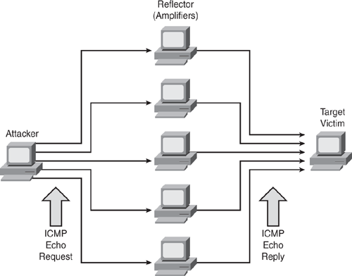
The smurf attack, also commonly known as ICMP flooding, has two victims: a target victim and a reflector or amplifier. The attacker sends a large number of ICMP echo requests (pings) to the broadcast address of the reflector subnet. The source addresses of these packets are forged (spoofed) to be the address of the target victim. For each packet sent by the attacker, hosts on the reflector subnet respond to the target victim, thereby flooding the victim network and causing congestion that results in a denial of service as shown in Figure 7-1.
A similar attack called fraggle uses directed broadcasts in the same technique, sending UDP echo requests instead of ICMP echo requests. Fraggle usually achieves a smaller amplification factor than smurf and is much less popular.
Figure 7-1 illustrates how a smurf attack works. In such an attack, a large number of ICMP echo request packets are sent to the reflectors (using the IP broadcast address) with a spoofed source IP address of the victim host. When the reflector hosts receive the ICMP echo packet, they respond with an ICMP echo-reply packet to the victim address, thereby causing an ICMP flood situation.
Example 7-1 shows an extended access list with permit statements to identify smurf or fraggle attacks.
access-list 101 permit icmp any any echo access-list 101 permit icmp any any echo-reply access-list 101 permit ip any any ! interface <suspected interface> ip access-group 101 in |
Note
Characterization ACLs do not filter out traffic; all the ACL entries are permit statements because the objective is to categorize the traffic.
As shown in Figure 7-1, two possible victims are affected in this attack and need to be identified accordingly:
Use the show ip access-list command to display the access-list packet match statistics to identify the potential threat.
The show ip access-list command output in Example 7-2 shows a large number of ICMP echo reply packets, which is an indication of a potential ICMP flood or smurf attack on the ultimate target victim rather than the reflector.
Router# show ip access-list Extended IP access list 101 permit icmp any any echo (5 matches) permit icmp any any echo-reply (2198 matches) permit ip any any (11205 matches) |
When the show ip access-list command output indicates a large number of ICMP echo requests instead of echo replies, as shown in Example 7-3, this indicates that the network is being used as a reflector (amplifier). The same output could also mean that the network is experiencing a simple ICMP ping flood, not a smurf. In either case, if the attack is successful, both the egress and the ingress interfaces will be experiencing congestion with large packet counts on the interface. Furthermore, because of the amplification factor, the egress side will be more overloaded than the ingress side.
Router# show ip access-list Extended IP access list 101 permit icmp any any echo (5432 matches) permit icmp any any echo-reply (2 matches) permit ip any any (1904 matches) |
There are several ways to distinguish the smurf attack from the simple ping flood:
Smurf packets are sent to a directed broadcast address, rather than to a unicast address, whereas ordinary ping floods almost always use unicast. This can be checked in the addresses with the log-input keyword on the appropriate access list entry.
When experiencing a smurf reflector attack, a disproportionate number of output broadcasts in the show interface counters is displayed, and usually a disproportionate number of broadcasts are sent in the show ip traffic display. A standard ping flood does not increase the background broadcast traffic.
When experiencing a smurf reflector attack, there is more outbound traffic toward the uplink, as compared to the inbound traffic from the uplink. In general, there are more output packets than input packets on the suspected interface.
When a smurf reflector is closer to the intruder than the ultimate target, it is much easier to trace the attack. ISPs need to be closely involved in tracing such attacks. However, in other situations, the reflector may not be closer to the attacker than the target. The target could be on your own subnet with the reflector on the other side of the network. (The broadcast address does not determine the unicast destination that has been spoofed.)
To stop Cisco routers from being reflectors in such attacks, use the no ip directed-broadcast interface configuration command. This should be configured on each interface of all routers. Note that no ip directed-broadcast is now the default on all interfaces, beginning with Cisco IOS Software Version 12.0. This command drops any packets on the router that are sent to a directed broadcast address that causes multiple hosts to respond to the ICMP echo request.
You can use several techniques to prevent or minimize the impact of smurf and similar ICMP flood attacks, such as rate-limiting (Committed Access Rate [CAR]), a filter using access lists, and Unicast Reverse Path Forwarding (uRPF) and IP Source Guard features, as discussed in the "IP Spoofing Attacks" section later in this chapter.
There are many variations of SYN flood attacks, with the most common being a situation in which a target machine is flooded with TCP SYN connection requests. In most cases, the source addresses and source TCP ports of the connection request packets are randomized and spoofed. The objective is to force the target host to maintain TCP state information for a large number of incomplete connections (half-open connections), also called embryonic connections, which are illustrated in Figure 7-2.
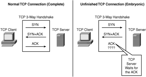
SYN flood attacks are sometimes easy to identify because the target host (such as the HTTP or SMTP server) becomes extremely slow, crashes, or hangs. SYN floods are not the only vector; several other vectors exist that are aimed in a similar flooding attack. Most people focus on SYN floods as a critical security attack vector. In reality, some SYN flood mitigation paths open the door for other TCP-based attack vectors.
TCP attack vectors are varied and include the following:
SYN Flood
ACK Flood
SYN+ACK Flood
SYN+RST Flood
RST Flood
Established Flood
FIN Flood
TCP Options Flood
X-Tree Flood
There are two major types of SYN-flood attacks:
Nonspoofed source addresses: Easy to trace, usually launched from compromised hosts (user workstations, servers, and the like)
Spoofed source addresses: Difficult to trace, when spoofing invalid addresses from Bogon space (unallocated address range) or valid addresses from someone else's address blocks
SYN Round Trip Time (RTT) is the interval between the sending of SYN+ACK and reception of the corresponding ACK from the other host (receiver). A successful SYN flood occurs when the number of simultaneous SYNs exceeds the capacity of the victim's TCP Listen queue and the rate of SYNs exceeds the victim's ability to clear the SYN_RCVDs in an interval less than the SYN+ACK RTT. The objective of the attack is to crowd out valid SYN_RCVDs before the client's ACK has a chance to get to the server. If an ACK is received, and there is no available SYN_RCVD waiting, the connection fails and the DoS is successful, as depicted in Figure 7-3.
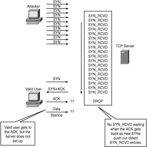
In summary, to successfully SYN-flood, the attacker must achieve the following:
Fill and overflow the TCP server's memory so that the oldest SYN_RVCD entries are flushed.
Fill the TCP queue faster than the typical SYN+ACK RTT so that valid customer SYN_RVCD entries are crowded out.
Example 7-4 shows an extended access list with permit statements to identify a TCP SYN attack. The TCP permit statement has several other options, such as matching FIN, URG, RST flags or established connections, or checking fragment packets.
access-list 101 permit tcp any any syn access-list 101 permit ip any any ! interface <suspected interface> ip access-group 101 in |
Use the show ip access-list command to display the access-list packet match statistics to identify the SYN attack.
The output in Example 7-5 shows a large number of TCP SYN packets, an indication of a potential SYN flood to a target victim. The only nonattack condition that creates this signature is a massive overload of genuine TCP connection requests.
Router# show ip access-list Extended IP access list 101 permit tcp any any syn (13174 matches) permit ip any any (438 matches) |
Many features are available that you can use to reduce the impact of SYN floods. The effectiveness of these features depends on the environment; therefore, you should carefully examine these solutions. Some techniques available to prevent or minimize the impact of SYN flood attacks include the following:
Rate-limiting (CAR).
Context-Based Access Control (CBAC).
TCP Intercept.
On security appliances such as PIX firewalls, static and nat commands provide an option to monitor and control half-open embryonic connections. For more details, refer to static command in PIX documentation.
Antispoofing: Do not allow traffic claiming to be sourced from customer IP blocks to ingress from the uplink or Internet.
Anti-bogon: Do not allow traffic claiming to be sourced from reserved addresses or from an IPv4 block that has yet to be allocated by the Internet Assigned Numbers Authority (IANA).
A source-based remote triggered black hole (RTBH) filtering technique can also be used as a SYN flood mitigation tool. This feature provides real-time defense against DDoS attacks by using a combination of IP routing features. To learn more about this technique, refer to the following white paper: www.cisco.com/warp/public/732/Tech/security/docs/blackhole.pdf.
Source tracking is the process of tracing packet streams from the victim back to the point of origin to find the source of the attack through the network path. Although an ACL is a common tool and can be leveraged to trace back attacks, it has a potential performance impact when applied in a production network environment. IP source tracker provides an easier, more scalable alternative to ACLs for tracking DoS attacks, and it generates all the required information to trace the ingress point of an attack into the network with minimal performance penalty.
The following steps illustrate how IP source tracker works for tracking DoS attacks.
Step 1. | After a host is identified as under attack, enable the IP source tracker feature concurrently to track multiple destination IP addresses on the router by using the ip source-track command from the global configuration mode. |
Step 2. | The router creates a special Cisco Express Forwarding (CEF) entry for the destination address being tracked. |
Step 3. | The CPU collects all the necessary data in the context of the traffic flow for each tracked IP address in an easy-to-use format and periodically exports this data. |
Step 4. | The periodically exported data can be viewed by using the show ip source-track <ip-address> command to display detailed information for each input interface, including detailed statistics of the traffic destined to each IP address. To display a summary of the flow information, use the show ip source-track summary command. |
Step 5. | Detailed statistics provide a breakdown of the traffic to each tracked IP address. This information allows you to determine which upstream router to analyze next and makes a hop-by-hop traceback to the attacker possible. |
Step 6. | These steps are repeated on each upstream router until the source of the attack is identified. |
Step 7. | Apply appropriate mitigation techniques to stop or minimize the attack. |
Example 7-6 shows how to enable IP source tracking on a router to collect traffic flow statistics to host address 10.1.1.1 for two minutes, create an internal system log entry, and export packet and flow information for viewing to the route processor every 30 seconds.
Router(config)# ip source-track 10.1.1.1 Router(config)# ip source-track syslog-interval 2 Router(config)# ip source-track export-interval 30 |
Example 7-7 shows detailed information of the flows per-destination IP address being tracked.
Router# show ip source-track 10.1.1.1 Address SrcIF Bytes Pkts Bytes/s Pkts/s 10.1.1.1 PO0/0 119G2553M 5619921 156821 |
Note that the previously listed output indicates that interface POS 0/0 is the potential upstream attack path from which the attack is originating. After the next-hop is determined, it is highly recommend to disable ip source-track on the current router and enable it on the upstream router to track the next preceding hop.
Note
The IP source tracker feature was introduced in Cisco IOS Release 12.0(21)S and was integrated into Cisco IOS Release 12.3(7)T and later. Use the Feature Navigator tool to check platform support and corresponding Cisco IOS Software image at www.cisco.com/go/fn.
As discussed earlier, many network attacks rely on an intruder falsifying, forging, or spoofing the source addresses in IP datagrams. It is very important and best practice to implement antispoofing mechanisms to prevent spoofing wherever feasible.
Antispoofing measures should be taken at every point in the network where practical, but they are usually easiest to implement and most effective at the borders among large address blocks or among domains of network administration.
Apply antispoofing controls described in RFC 2827, "Network Ingress Filtering: Defeating Denial of Service Attacks Which Employ IP Source Address Spoofing," and in Best Current Practices (BCP 38). The RFC dictates that no IP packets should be sent out to the Internet with a source address other than the addresses that have been allocated to your network.
In summary, the antispoofing implementation is used to
Deny incoming packets if source address is allocated to your network
Deny outbound packets if source address is not allocated to your network
Unfortunately, there is no simple list of commands to provide as a template to configure antispoofing access lists, because networks vary and configuration depends on the network boundaries and address space allocations. However, the basic objective is to drop packets that arrive on interfaces that are not viable paths from the supposed source addresses of those packets. For example, on a two-interface router connecting a corporate network to the Internet, any datagram that arrives on the Internet interface whose source address field claims it originates from a host on the corporate network should be discarded. Similarly, any datagram exiting the corporate network whose source address field claims to be anything other than the allocated address space of the corporate network should be discarded. Figure 7-4 depicts a basic guideline to configure antispoofing access lists.
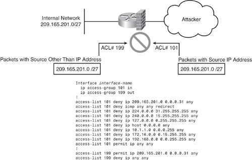
In Figure 7-4, ACL 101 is applied inbound and ACL 199 is applied outbound on the external interface. ACL 101 drops any inbound packets with forged (spoofing) source addresses as the internal allocated address space or trusted hosts. ACL 199 ensures that none of the outgoing packets change their IP addresses to one not belonging to the internal allocated address space. In addition to the antispoofing entries, Figure 7-4 shows ACL 101 with additional deny statements that drop datagrams with broadcast or multicast source addresses, and datagrams with the reserved loopback address and the RFC1918 addresses as a source address.
It is usually appropriate for an antispoofing access list to filter out all ICMP redirects regardless of source or destination address. These are just basic guidelines and can be further fine-tuned with other filtering such as anti-bogon, traffic claiming to be sourced from reserved addresses, or from an IPv4 block that has yet to be allocated by IANA.
In general, antispoofing filters are best deployed as input access lists; that is, packets must be filtered at the arriving interfaces, not at the interfaces through which they exit the router. The input access list also protects the router itself from spoofing attacks, whereas an output list protects only devices behind the router.
Unicast Reverse Path Forwarding (uRPF) is another common technique used to mitigate source address spoofing. When uRPF is used, the source address of IP packets is checked to ensure that the route back to the source uses the same interface that the packet arrived on. If the input interface is not a feasible path to the source network, the packet will be dropped. The uRPF feature is discussed later in this chapter.
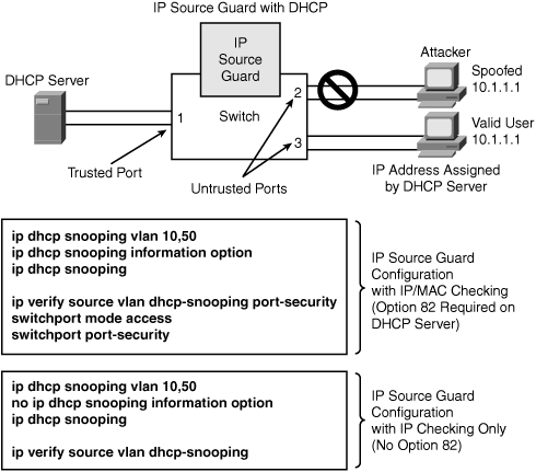
IP Source Guard is a Layer 2 security feature that prevents IP spoofing attacks by restricting IP traffic on untrusted Layer 2 ports to clients with an assigned IP address. This feature works by filtering IP traffic with a source IP address other than that assigned via Dynamic Host Configuration Protocol (DHCP) or static configuration on the untrusted Layer 2 ports. The IP Source Guard feature works in combination with the DHCP snooping feature available on Catalyst switches and is enabled on untrusted Layer 2 ports. (DHCP snooping is discussed in Chapter 4, "Security Features on Switches" with configuration examples.)
As shown in Figure 7-5, when you are using the IP Source Guard feature in a DHCP-enabled environment, all traffic is blocked on the switch port except for the DHCP packets that are captured by the DHCP snooping process. The DHCP packets flowing between the DHCP client and the server are monitored, and the monitoring creates a binding table that lists IP-to-MAC mapping on each switch port. This allows the switch to know which port is connected with what source MAC address and the assigned IP address. If DHCP is not used, a static IP source binding map can be configured by the user. With the help of this IP-to-MAC binding table, a per-port VLAN Access Control List (PACL) is installed (PACL is a security ACL applied on Layer 2 switch ports) that denies traffic other than spoofed source, based on the binding table. This filtering mechanism protects against IP and MAC address spoofing.
Note
The IP Source Guard feature will not prevent an MITM type of attack. Use Dynamic ARP Inspection (DAI) to prevent MITM, as discussed in the section "ARP Spoofing Attack" later in this chapter.
Cisco IOS provides an unparalleled and comprehensive set of Quality of Service (QoS) features. These tools can be leveraged in the context of security implementations and mitigating network attacks. QoS technologies are becoming increasingly important and critical to maintaining network availability and security.
Several QoS techniques exist for various types of application protocols because not all techniques work for all protocols. These methods apply in different phases of a protocol transition; for example, packets are first characterized (classified) using classification and marking techniques, then policed and dropped, or other action is taken depending on the requirement. With the QoS technology framework, a proactive approach (explicitly protecting critical traffic) is more effective than a reactive approach (trying to identify and squelch bad traffic). It is recommended that the minimum first step when deploying QoS techniques to protect a network against DoS attacks should be to explicitly protect core routing, infrastructure devices, and mission-critical data traffic.
Traffic classification is a method used to partition traffic into groups or classes of service (CoS) dividing network traffic into different categories. Traffic classification is followed by traffic marking, which is a method of identifying certain traffic types for unique handling and allowing the marking (that is, set or change) of a value (attribute) for the traffic belonging to a specific class. Traffic classification and traffic marking are closely related and can be used together. Traffic marking can be viewed as an additional action, specified in a policy map, to be taken on a traffic class.
As mentioned earlier, various QoS techniques are available for traffic classification and marking. Examples of classification and marking techniques include Class-Based Weighted Fair Queuing (CBWFQ), Committed Access Rate (CAR), Modular QoS CLI (MQC), and Network-Based Application Recognition (NBAR). These QoS mechanisms can also be effectively used in combination. For example, MQC and NBAR with policing techniques can be used in combination to give more granular control while regulating normal traffic flows. Using tools already available in Cisco IOS Software, these solutions help provide proactive mitigation solutions.
CAR is a multifaceted feature that embodies a rate-limiting feature for policing traffic, in addition to its packet classification and marking feature. CAR can be used to mark packet streams, for example, setting different IP precedence for selected packets entering or exiting the network. As the packet traverses through the network, devices within the path can then use the adjusted IP precedence to determine how to treat the marked traffic.
The policing feature of CAR controls the maximum rate of traffic sent or received on an interface (bandwidth management) for a network specifying traffic handling policies, when the traffic either conforms to or exceeds the specified rate limits. This is achieved by ensuring that traffic falling within specified rate parameters is sent; however, packets that exceed the acceptable amount of traffic are dropped or sent with a different level of priority. By default, the action for traffic exceeding the specified rate limits is to drop or mark down packets.
Simple techniques such as CAR sometimes produce the best results. CAR propagates bursts. It does not perform traffic shaping, and therefore does no buffering and adds no delay. CAR can be applied to all traffic or a subset of the traffic selected by an access-list. CAR performs best when configured on interfaces at the edge of a network to limit traffic into or out of the network.
CAR provides several fundamental capabilities, as depicted in Figure 7-6. CAR examines traffic received on an interface or a subset of selected traffic by using access list criteria, or all IP traffic, or traffic group by a classification tag such as IP precedence. It then compares the rate of the traffic to a configured token bucket and executes the action policy based on the result. For example, CAR will drop the packet or rewrite the IP precedence by resetting the type of service (ToS) bits.
The information in Figure 7-6 is taken from Cisco security presentation on "Committed Access Rate."
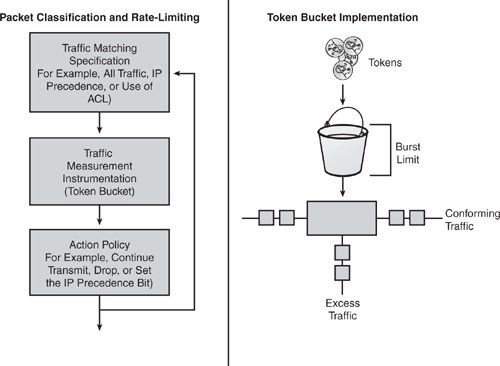
CAR utilizes a token bucket measurement. Token bucket parameters include the committed rate, the normal burst size (to handle temporary bursts over the rate limit without penalty), and the excess burst size. Tokens are filled into the bucket at the committed rate; that is, if the committed rate is 1 MB, this is the number of tokens inserted into the bucket. Think of it as advance token deposit or token repository. The depth of the bucket is the burst size. When traffic arrives at the bucket and sufficient tokens are available, the traffic is said to conform, and the corresponding number of tokens are removed from the bucket (tokens spent are gone). If sufficient tokens are not available (repository is empty), the traffic is said to exceed.
Example 7-8 shows how CAR can be used to limit the rate for specific types of protocols to ensure sufficient capacity for other traffic, including mission-critical applications. Two access lists are created to classify the web and ICMP traffic, so that they can be handled separately by CAR. Note that multiple rate-limit statements can be configured in each direction, and they will be processed top down. The following example shows outbound rate limiting. Inbound rate limiting can also be added.
|
Code View: Router(config)# access-list 101 permit tcp any any eq www Router(config)# access-list 102 permit icmp any any Router(config)# interface <interface> Router(config-if)# rate-limit output access-group 101 10000000 24000 32000 conform- action set-prec-transmit 5 exceed-action set-prec-transmit 0 Router(config-if)# rate-limit output access-group 102 50000 25000 30000 conform- action set-prec-transmit 0 exceed-action drop Router(config-if)# rate-limit output 4000000 16000 24000 conform-action continue exceed-action drop |
Let's look more closely at the steps involved in Example 7-8:
Use the show interfaces <interface> rate-limit command to verify the configuration and monitor CAR statistics.
Cisco modular QoS command-line interface (CLI), referred to as MQC, provides a modular and highly extensible framework that allows users to create hierarchical traffic policies to deliver extremely powerful and scalable solutions. A traffic policy contains a traffic class and one or more QoS features. A traffic class is used to classify (partition) traffic, whereas the QoS features determine how to treat the classified traffic. With the scalability and hierarchical policies, MQC can deliver security and attack mitigation solutions that can virtually be used for any type of attack mitigation.
MQC provides comprehensive classification and marking solutions with a complete set of capabilities to classify and mark traffic based on any Layer 2 or Layer 3 fields. MQC extends the capability to intelligently classify Layer 4 through Layer 7 protocols, using the integrated Network Based Application Recognition (NBAR) technology in the IOS. MQC offers a single-rate and two-rate policer, which allows for packet re-marking (Layer 2 and Layer 3) or dropping policies to control traffic at the network edges/aggregation points.
The MQC allows for the Unconditional Packet Discard feature in which traffic that matches certain criteria can be unconditionally dropped. This feature allows discarding (drop action inside a traffic class in a policy map) without any further system processing and almost no performance impact. This function is very useful in the security context because it allows the user to discard any packets for nonessential applications (such as Internet browsing applications or unauthorized file-sharing P2P applications) while allocating system resources to more essential applications.
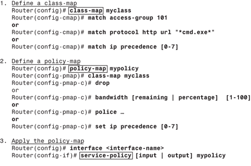
Configuring MQC is a three-step process, which is outlined in the list that follows and depicted in Figure 7-7.
1. | Define a class-map: The first step in MQC deployment is to identify the interesting traffic (classifying the packets). This step defines groupings of network traffic by using various classification tools, such as ACLs, IP addresses, IP precedence, IP Differentiated Services Code Point (DSCP) values, IEEE 802.1p, MPLS EXP, and Cisco Network-Based Application Recognition (NBAR) technology. |
2. | Define a policy-map: After the traffic has been identified, a policy-map dictates what action is to be taken. This step can be considered the actual construction of an MQC through use of a policy-map to perform specific functions. Examples of functions are queuing, dropping, policing, shaping, bandwidth control, or marking IP precedence or DSCP values. |
3. | Apply the policy-map: The final step is to apply the policy-map to the desired interfaces or subinterfaces. Each interface can have up to two policy-maps applied, each in one direction (inbound and outbound). |
The show policy-map interface <interface-name> command can be used to display the packet statistics of all classes that are configured for all service policies on the specified interface.
The Cisco IOS Traffic Policing features allow the control and filtering of the incoming and outgoing traffic rate on an interface, as well as network bandwidth management through the token bucket algorithm. Traffic that falls within the defined parameters is sent, whereas traffic that exceeds or violates the parameters is dropped or sent with a different priority.
Several policing techniques are available within the Traffic Policing technology:
Traffic Policing (Single-Rate Policer): Single-Rate Policer controls the input or output traffic rate for class-based user-defined criteria.
Two-Rate Policer: Two-Rate Policer enforces Traffic Policing according to two separate rates: committed information rate (CIR) and peak information rate (PIR). These two rates can be specified along with their corresponding values by using the cir and pir keywords in the police command.
Policer Enhancements—Multiple Actions: This feature further extends the functionality of the Traffic Policing feature (Single-Rate Policer) and the Two-Rate Policer feature. With both features, there is a limitation to specify only one conform action, one exceed action, and one violate action. With the new Policer Enhancement "Multiple Actions" feature, multiple conform, exceed, and violate actions for the marked packets can now be specified.
Percentage-Based Policing and Shaping: This feature provides the capability to configure Traffic Policing and traffic shaping based on a percentage of bandwidth available on the interface by using the police (percent) and shape (percent) commands.
Color-Aware Policer: The Color-Aware Policer feature is a method of Traffic Policing using an enhanced "color-aware" technique. The packet color classification is based on packet-matching criteria defined for two user-specified traffic classes—the conform-color class and the exceed-color class. These two traffic classes are created using the conform-color command, and the metering rates are defined using the police command. This feature is not available on all platforms. Use Feature Navigator to check platform and IOS support.
Configuring Traffic Policing is similar to configuring MQC, as described in the previous section. The tasks of configuring each of the Traffic Policing features that are listed previously are essentially the same; that is, you configure by using the MQC (as shown in the previous section) to create a class-map and policy-map. Then, using the police command, you configure the various traffic-policing features previously discussed under a specific class within that policy-map, as shown in Figure 7-7, and attach the policy-map to the interface. Traffic Policing can be configured at any level of the policy-map hierarchy—that is, at the primary level, the secondary level, or the tertiary level. Example 7-9 shows a basic configuration applying Traffic Policing (Single-Rate Policing).
|
Code View: Router(config)# class-map myclass Router(config-cmap)# match access-group 101 Router(config-cmap)# exit Router(config)# policy-map mypolicy Router(config-pmap)# class-map myclass Router(config-pmap-c)# police 8000 1000 1000 conform-action transmit exceed-action drop violate-action drop Router(config-pmap-c)#exit Router(config-pmap)#exit Router(config)# interface <interface-name> Router(config-if)# service-policy [input | output] mypolicy |
The NBAR feature adds application-level intelligent classification capability to the network infrastructures. NBAR is a classification engine that recognizes a variety of applications and protocols from Layer 4 through Layer 7, including web-based and other difficult-to-classify protocols that utilize static and dynamically assigned TCP and UDP port numbers. NBAR classification extends by looking beyond the TCP/UDP port numbers of a packet and packet headers. This capability is called subport classification. NBAR looks into the TCP/UDP payload and classifies packets on the basis of the content within the payload, such as transaction identifier, message type, or other similar data.
NBAR classifies the following three types of protocols:
TCP and UDP protocols that use statically assigned port numbers
TCP and UDP protocols that use dynamically assigned port numbers, requiring stateful inspection
Non-TCP and non-UDP IP protocols such as IPsec (ESP/AH) or ICMP
NBAR includes a special Protocol Discovery feature that provides an easy way to discover application protocols traversing a network at any given time. Protocol Discovery can be applied to interfaces by using the ip nbar protocol-discovery command under the interface configuration mode and can be used to monitor both input and output traffic. The Protocol Discovery feature captures important per-protocol statistics supported by NBAR, such as total number of input and output packets and bytes, and input and output bit rates. These statistics assist in developing traffic classes and policies. The show ip nbar protocol-discovery command displays the statistics for all interfaces on which Protocol Discovery is enabled.
An external PDLM can be loaded on the router at runtime using the ip nbar pdlm <pdlm-name> command from the global configuration mode, extending and enhancing the classification engine for the many existing and emerging application protocols in the NBAR list of protocols. PDLMs can also be used to enhance an existing protocol recognition capability. PDLMs allow NBAR to recognize new protocols without requiring a new Cisco IOS image or a router reload. The show ip nbar pdlm command displays all currently loaded PDLMs. Example 7-10 shows the current PDLM loaded from flash memory.
Router# show ip nbar pdlm
The following PDLMs have been loaded:
flash:gnutella.pdlm
flash:kazaa2.pdlm
flash:edonkey.pdlm |
Similar to the other techniques discussed earlier in this chapter, NBAR is configured through the MQC framework. Example 7-11 shows a class-map "myclass" using the NBAR technique to classify peer-to-peer (P2P) file-sharing network traffic as its matching criterion using the match protocol commands. P2P traffic is bandwidth intensive, and most networks would like to manage them. The example shows that P2P can be blocked using the drop command or policed down to the average rate of 8000 bits per second with a normal burst size of 1000 bytes and an excess burst size of 1000 bytes.
The long list of supported protocols available in the match protocol command includes HTTP, HTTPS, FTP, IMAP, POP3, SMTP, BGP, RIP, EIGRP, ICMP, KAZAA, NAPSTER, and PCANYWHERE.
|
Code View: Router(config)# class-map myclass Router(config-cmap)# match protocol fasttrack Router(config-cmap)# match protocol napster Router(config-cmap)# match protocol gnutella Router(config-cmap)# match protocol edonkey Router(config-cmap)# match protocol kazaa2 Router(config-cmap)# exit Router(config)# policy-map mypolicy Router(config-pmap)# class-map myclass ! Define Drop action Router(config-pmap-c)# drop ! OR Perform Class-based Policing Router(config-pmap-c)# police 8000 1000 1000 conform-action transmit exceed-action drop Router(config-pmap-c)#exit Router(config-pmap)#exit Router(config)# interface <interface-name> Router(config-if)# service-policy [input | output] mypolicy |
The show ip nbar port-map [protocol-name] command can be used to display the TCP/UDP port numbers used by NBAR to classify a given protocol.
TCP Intercept is another important security feature integrated into Cisco IOS software, which is used to protect TCP servers from SYN-flooding attacks. As discussed earlier in this chapter, a SYN-flooding attack occurs when an attacker attempts to flood a TCP server with requests for connection. Because these messages have unreachable or spoofed return addresses, the connections are not able to fully establish. The resulting volume of incomplete half-open connections eventually overwhelms the TCP server and can cause it to deny regular service to valid user requests, thereby preventing legitimate users from connecting to a website, accessing e-mail, using FTP service, or any other TCP-based application.
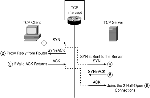
Figure 7-8 illustrates how the TCP Intercept feature works by intercepting and validating all incoming TCP connection requests flowing between a TCP client and TCP server. In the intercept mode, the TCP Intercept engine intercepts TCP synchronization (SYN) packets from clients to servers that match an extended access list. The software establishes a connection with the client on behalf of the destination server (proxying the SYN) and, if successful, establishes the connection with the server on behalf of the client, thereby transparently knitting together the two half-connections. This mechanism protects against any connection attempts from unreachable or spoofed hosts. The software continues to intercept and forward packets (inline) throughout the duration of the connection.
In the event of illegitimate requests, the aggressive timeouts on half-open connections and thresholds on TCP connection requests protect destination servers while continuing to forward legitimate requests.
TCP intercept operates in two modes: the passive watch mode or the default active intercept mode. In watch mode, all connection requests are allowed to pass through the router with the software passively watching the connection that is being established. If a connection fails to establish in a configurable interval, the software then intervenes and terminates the connection attempt. Whereas in intercept mode, the software actively intercepts all incoming connection SYN requests and responds on behalf of the server with an SYN-ACK waiting for an ACK from the server. When an ACK is received from the TCP server, the original SYN is sent to the server and the software performs a three-way handshake with the server. When this is complete, the two half-connections are joined.
To configure the TCP Intercept feature, you need to first define an access list that instructs the intercept engine to intercept and validate either all requests or only specific networks or specific destination servers. Generally, the access list should have the source as any and define specific destination networks or servers. This will provide protection for destination host(s) and not the source. If no access list match is found, the router allows the request to pass with no further action.
Example 7-12 defines extended IP access list 101, instructing the TCP Intercept engine to intercept packets for all TCP servers on the 10.1.1.0/24 subnet. The example also tunes the aggressive threshold trigger values to 400 and 500 for low and high incomplete connections, respectively.
Router(config)# access-list 101 permit tcp any 10.1.1.0 0.0.0.255 Router(config)# ip tcp intercept list 101 Router(config)# ip tcp intercept max-incomplete low 400 Router(config)# ip tcp intercept max-incomplete high 500 |
The ip tcp intercept mode {intercept | watch} command in global configuration mode can be used to set the TCP intercept mode.
The show tcp intercept connections command displays incomplete connections and established connections, and show tcp intercept statistics displays TCP intercept statistics.
The TCP Intercept feature is also available on the PIX 500, ASA 5500, and FWSM firewall software to help protect servers behind the firewall from SYN-flood attacks. The feature allows for configuring two parameters:
The maximum number of established connections allowed to a TCP server
The maximum number of incomplete half-open (embryonic) connections to a TCP server
When the embryonic connection limit is reached, the firewall responds to every SYN packet sent to the server with a SYN+ACK and does not pass the SYN packet to the internal server. If the external device responds with an ACK packet, the firewall knows it is a valid request and not part of a SYN attack. The firewall then establishes a connection with the internal server and joins the client connections passively. If the firewall does not get an ACK back from the server, it aggressively times out that embryonic connection. Figure 7-8 illustrates how this works.
Example 7-13 shows a static translation on PIX for an internal TCP server with the embryonic limit set to 100 and the Max Connection limit set to 1000. Most Windows platforms allow a maximum of 128 half-open (embryonic) connections, so when setting the embryonic limit on the static, use a value less than the maximum embryonic limit allowed by the server operating system.
PIX(config)# static (inside, outside) 209.165.201.1 10.1.1.1 netmask
255.255.255.255 1000 100 |
The nat command offers the same feature. Example 7-14 shows how configuring the nat command is similar to configuring the TCP Intercept.
PIX(config)# nat (inside) 1 10.1.1.0 255.255.255.0 1000 100 |
Policy-based routing (PBR) provides a method for overriding the information available in the IP routing table and can be configured to forward (route) packets based on other criteria defined in policies, such as IP addresses, port numbers, application, and the length/size of the packet. PBR can also be used for packet classification and marking with IP precedence values in the Type of Service (ToS) field of the IP header. PBR gives more granular control over routing of packets by extending and complementing the existing mechanisms provided by routing protocols.
With the capability to control a data path, in the event of an attack, PBR can be used as a security tool to divert traffic and for scrubbing or managing congestion. PBR can also be used as a mitigation tool to match the attack traffic and drop it. Example 7-15 shows sample configurations for both these scenarios.
PBR allows performing the following tasks:
Classifying traffic based on the extended access list to identify the match criteria
Rewriting or changing header options such as IP precedence, DF, or ToS bits, influence the next-hop address or interface
Example 7-15 shows configuration of a PBR and provides details on how to route traffic from different sources to different next-hops. Traffic can be routed by overwriting the path devised by an IP routing table and setting various parameters in the packet header, such as the IP precedence or the ToS bit. All packets arriving on the specified interface matching the match clauses will be subject to the action defined in the set command.
The example shows that all packets arriving from source 1.1.1.1 are forwarded to the next-hop address at 11.11.11.11 with the Precedence bit set to priority, whereas packets arriving from source 2.2.2.2 are forwarded to a different next-hop address at 22.22.22.22 with the max-throughput TOS (4) bit set. The example also shows that all TCP packets that arrive with a minimum and maximum packet length of 100 are sent to the Null 0 interface (black holing the packets). PBR is then applied on a particular interface.
Router(config)# access-list 1 permit ip 1.1.1.1 Router(config)# access-list 2 permit ip 2.2.2.2 Router(config)# access-list 101 permit tcp any any Router(config)# route-map mymap permit 10 Router(config-route-map)# match ip address 1 Router(config-route-map)# set ip precedence priority Router(config-route-map)# set ip next-hop 11.11.11.11 Router(config-route-map)# exit Router(config)# route-map mymap permit 20 Router(config-route-map)# match ip address 2 Router(config-route-map)# set ip tos max-throughput Router(config-route-map)# set ip next-hop 22.22.22.22 Router(config-route-map)# exit Router(config)# route-map mymap permit 30 Router(config-route-map)# match ip address 101 Router(config-route-map)# match length 100 100 Router(config-route-map)# set interface null 0 Router(config-route-map)# exit Router(config)# interface <interface-name> Router(config-if)# ip policy route-map mymap |
Note that PBR is applicable for inbound traffic when configured on the specified interface. By default, packets generated by the router are not policy routed. To enable local PBR for such packets, the additional ip local policy route-map <map-name> command from the global configuration mode is required.
The show ip policy and show route-map commands can be used to verify PBR configuration and display packet statistics for each policy.
The uRPF feature is a security tool that helps mitigate source IP address spoofing by discarding IP packets that lack a verifiable IP source address in the IP routing table. Several DoS/DDoS attacks employ forging or rapidly altering source IP addresses to navigate around threat detection and filtering mechanisms. uRPF technique thwarts any attempts of DoS attacks by relying on IP spoofing. uRPF should be deployed at the network edge or the border/gateway device on the network.
There are two flavors of uRPF implementation:
Strict Mode complying with RFC 2827 filters on Network Ingress Edge and Best Current Practices (BCP 38)
As illustrated in Figure 7-9, the router examines all arriving packets received on the uRPF-enabled interface and will only forward packets that pass the uRPF check; that is, the source address appears in the routing table and matches the interface on which the packet was received. In other words, source IP packets are checked to ensure that a packet's return path uses the same interface it arrived on. If the source IP address is unknown and not reachable through the interface on which the packet was received, the packet is dropped by default. Because the lookup relies on the presence of the Forwarding Information Base (FIB), this "look backward" capability works only when Cisco Express Forwarding (CEF) is enabled on the router. CEF generates the FIB as part of its operation.
The information in Figure 7-9 is taken from the Cisco security presentation on "Unicast Reverse Path Forwarding."
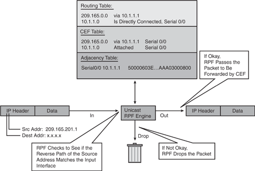
The uRPF enhances with the ACL logging capability by enabling reverse path forwarding (RPF) check in a pass-through mode. In this mode, all RPF violations are logged using the ACL log-input feature. If a packet fails RPF check, the ACL is checked to determine whether the packet should be dropped (using a deny ACL) or forwarded (using a permit ACL). The ACL logging counter and match counter statistics are incremented to reflect statistics for packets with spoofed IP addresses.
Example 7-16 shows how to configure uRPF on an interface with the ACL logging feature. Packets sourced from 10.1.1.0/24 subnet arriving at serial0/0 and failing the uRPF check are logged by the ACL log statement and dropped by the ACL deny action. Packets sourced from 172.16.1.0/24 subnet arriving at serial0/0 and failing the uRPF check are logged by the ACL log statement and forwarded by the ACL permit action.
|
Code View: Router(config)# access-list 101 deny ip 10.1.1.0 0.0.0.255 any log-input Router(config)# access-list 101 permit ip 172.16.1.0 0.0.0.255 any log-input Router(config)# interface <interface-name> Router(config-if)# ip verify unicast reverse-path 101 |
The show ip interface <interface-name> command displays uRPF statistics for dropped or suppressed packets for the specified interface and can be used with the show ip access-list command to detect IP address spoofing. If ACL logging is enabled, the data logs can be reviewed to gather additional information about the network attack, as shown in Example 7-17.
Router# show ip interface <interface-name> ... IP verify source reachable-via RX, allow default, ACL 101 56 verification drops 192 suppressed verification drops ! Router# show ip access-lists 101 Extended IP access list 101 deny ip 10.1.1.0 0.0.0.255 any log-input (56 matches) permit ip 172.16.1.0 0.0.0.255 any log-input (192 matches) |
To verify whether uRPF is operational, use the show cef interface <interface-name> command, as shown in Example 7-18.
Router# show cef interface <interface-name> Serial0/0 is up (if_number 3) ... IP unicast RPF check is enabled IP CEF switching enabled |
The show ip traffic command can be further used to display additional packet counter information for packets dropped because of uRPF checks, as shown in Example 7-19.
Router# show ip traffic IP statistics: ... Drop: 3 encapsulation failed, 0 unresolved, 0 no adjacency 0 no route, 0 unicast RPF, 0 forced drop |
NetFlow is a Cisco IOS feature that captures statistics on IP packets flowing through the router and is emerging as a primary security technology. Cisco is the pioneer in the NetFlow technology and the leader in IP traffic flow technology. NetFlow provides numerous applications and services: network traffic accounting, user and application monitoring, usage-based billing, link-usage, network planning, traffic profiling, traffic engineering, capacity planning, anomaly detection, and security and DoS monitoring capabilities.
As shown in Figure 7-10, Cisco NetFlow can be used primarily as a security analysis tool to identify and classify DoS attacks, viruses, worms, and network anomalies in real-time. The data can further be invaluable in forensic processes to gather details and comprehend security incidents. NetFlow is completely transparent to the existing network, including end stations, application software, and any devices on the network.
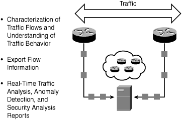
NetFlow is supported on most Cisco platforms via ASICs, Cisco IOS, and Cisco Catalyst Operating System (CatOS) software.
NetFlow classifies packets by the direction of their flow and identifies packet flows for both ingress and egress IP packets. Each flow is defined by its unique seven-key characteristics: ingress interface, IP protocol type, type-of-service (ToS), source and destination IP addresses, and source and destination port numbers, as shown in Example 7-21. The information gathered with NetFlow is like a phone bill that provides all the required information for traffic profiling and determining the "who, what, when, where, and how" of network traffic. NetFlow is usually deployed across the edge of a network to monitor peer interfaces, because these are the potential ingress points for most attacks.
Example 7-20 shows you how to enable NetFlow Switching for IP on a Cisco Router.
Router(config)# interface <interface-name> Router(config-if)# ip flow ingress <or> Router(config-if)# ip flow egress |
The ip flow ingress command is used to capture traffic being received by the interface, whereas the ip flow egress command is used to capture traffic being transmitted by the interface.
Note
For Cisco IOS prior to releases 12.2(14)S, 12.0(22)S, or 12.2(15)T, the ip route-cache flow command was used to enable NetFlow on an interface.
For Cisco IOS release 12.2(14)S, 12.0(22)S, 12.2(15)T, or later, the ip flow ingress command is used to enable NetFlow on an interface.
If CEF is not configured, NetFlow enhances the existing switching path (optimum switching).
If CEF is configured, NetFlow becomes a flow information gatherer and feature acceleration tool.
The router maintains current NetFlow cache to track all the flows passing through the device. The show ip cache flow command or the show ip flow interface command can be used to view a snapshot of the current flows stored in the router cache.
Example 7-21 shows a sample snapshot using the show ip cache flow command taken from the NetFlow cache. Note the large amount of ICMP flood (Protocol 01) and other valuable flow statistics and flow details (Src/Dest interface, Src/Dest IP and port, and so on).
|
Code View: Router# show ip cache flow
IP packet size distribution (72014968 total packets):
1-32 64 96 128 160 192 224 256 288 320 352 384 416 448 480
.003 .000 .000 .118 .000 .000 .000 .000 .000 .004 .000 .005 .000 .000 .000
512 544 576 1024 1536 2048 2560 3072 3584 4096 4608
.013 .000 .022 .067 .231 .000 .000 .000 .000 .000 .000
IP Flow Switching Cache, 53988 bytes
12 active, 2324 inactive, 66 added
364 ager polls, 0 flow alloc failures
Active flows timeout in 30 minutes
Inactive flows timeout in 15 seconds
last clearing of statistics never
Protocol Total Flows Packets Bytes Packets Active(Sec) Idle(Sec)
-------- Flows /Sec /Flow /Pkt /Sec /Flow /Flow
TCP-Telnet 3 0.0 1 44 0.0 0.6 15.3
TCP-BGP 1 0.0 1 59 0.0 0.0 15.0
UDP-other 13 0.0 48 586 0.0 138.5 14.2
ICMP 6720 143.7 17 592 252.6 6.7 10.6
SrcIf SrcIPaddress DstIf DstIPaddress Pr SrcP DstP Pkts
Fa0/0 10.1.1.1 Local 1.1.1.1 01 0000 0800 42K
Fa0/0 0.0.0.0 Null 255.255.255.255 11 0044 0043 360
Fa0/0 10.17.10.1 Local 192.168.5.161 01 0000 0000 423K
|
Additionally, NetFlow data can be exported from the NetFlow cache to an external collector for further analysis and can be used to map and identify the nodes under attack and also to determine the attack characteristics. To export NetFlow data, use the ip flow-export global configuration command.
Cisco has developed a robust ecosystem of NetFlow partners that have developed value-added functionality and reporting specialties, including accounting, traffic analysis, security, billing, network planning, and network monitoring. Many freeware tools are available that can analyze NetFlow data, including cflowd, flow-tools, and autofocus. Several GUI-based applications are available, such as Arbor, Mazu, and Adlex, which leverage NetFlow data for DoS attack detection and centralized reporting. Threat correlation tools such as Panoptis, used for anomaly detection, also take advantage of NetFlow data to detect, characterize, and mitigate DoS attacks.