The IPsec VPN framework provides network data encryption at the IP packet level (Layer 3), building scalable, highly secure, standards-based security solutions. IPsec provides data confidentiality, integrity, authentication, and anti-replay services. IPsec VPN is currently the only way to implement secure VPNs. The following sections provide guidelines for implementing IPsec VPN scenarios while using these IKE and IPsec standards.
Cisco offers extensive portfolios for IPsec VPN implementations on a wide range of products, including Cisco Routers, Catalyst 6500 Series Switches, Cisco ASA 5500 Series Adaptive Security Appliances, PIX 500 Series Firewall Appliances, and VPN3000 Concentrator Series Appliances.
The IPsec VPN is fully compliant with industry standards and best practices on all Cisco devices and can be implemented between any-to-any Cisco or non-Cisco devices.
IPsec VPN solutions can be divided into two major categories:
Site-to-Site IPsec VPN
 | Full Mesh |
 | Hub-and-Spoke |
 | DMVPN |
 | Static VTI |
 | GET VPN |
Remote Access IPsec VPN
 | Easy VPN |
 | Dynamic VTI |
Note
Dynamic Multipoint VPN (DMVPN) is discussed in Chapter 16, and Group Encrypted Transport (GET VPN) is discussed in Chapter 17.
Figure 15-16 depicts common IPsec VPN implementation scenarios.
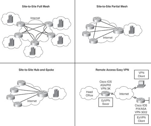
Table 15-8 is a quick comparison chart to show the various IPsec VPN implementation scenarios.
| Regular Crypto Maps | GRE/IPsec | DMVPN | Static VTI | Dynamic VTI | EzVPN | |
|---|---|---|---|---|---|---|
| Standard | RFC compliant | Yes, but uncommon | Yes, but uncommon | Yes, but uncommon | Yes, but uncommon | No |
| Main advantage | Basic, simple | Reroutes, deterministic convergence | Simple to deploy | Reroutes, deterministic convergence | Per tunnel features, dial integration | Simple to deploy |
| Main disadvantage | Basic, simple | Peers per device | Always active (no dialup) | Peers per device | New—limited experience | Hard to debug |
| Best used with | Non-IOS peers | Network-to-network | Hub-and-spoke/partial meshes | Network-to-network | Remote access | Remote access |
| Multicast support | No | Yes | Yes | Yes | Yes | No |
| IPv6 support | Not yet available | Inside only | No | Inside outside | Depends on client | No |
Site-to-site IPsec VPN offers integrated network intelligence and routing capabilities to deliver reliable transport mechanisms for complex mission-critical traffic, without compromising communications quality.
Site-to-site IPsec VPN provides an Internet-based WAN solution to securely connect remote offices, branch offices, home offices, or partner sites to central sites by using cost-effective Internet access rather than expensive dedicated WAN links, leased lines, or Frame Relay circuits.
Site-to-site IPsec VPN extends network resources by reducing WAN bandwidth costs while increasing connectivity speeds and maintaining quality and reliability over the Internet-based IPsec VPN solutions.
Site-to-site IPsec VPN also extends customized solutions, such as DMVPN, Routed GRE, and GET VPN technologies to cater to diverse network designs in full-mesh, hub-and-spoke, or any-to-any intersite connectivity environments.
Figure 15-17 illustrates a basic site-to-site IPsec tunnel establishment, and depicts the five-step modular flow, showing how an IPsec tunnel is established.
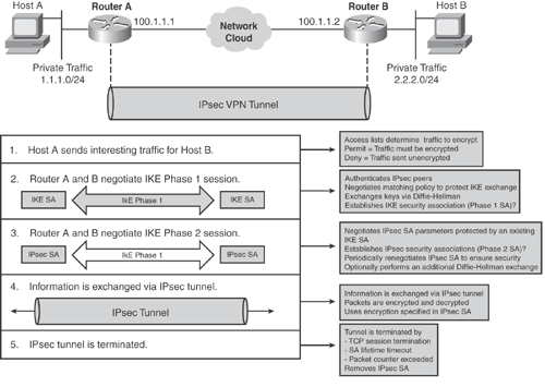
Based on Figure 15-17, Examples 15-2 and 15-3 show a basic site-to-site router-to-router IPsec configuration on Cisco IOS routers. The configuration shows the use of the ISAKMP profile with traditional crypto-map-based IPsec configurations.
hostname RouterA ! <..> ! Define Key-ring with the pre-shared key for individual spokes crypto keyring spokes pre-shared-key address 100.1.1.2 0.0.0.0 key cisco123 ! ! Define Phase 1 SA parameters crypto isakmp policy 10 encr 3des authentication pre-share group 2 ! ! Define ISAKMP profile for Lan-to-Lan spoke connection crypto isakmp profile isakmpprofile description LAN-to-LAN for spoke router connection keyring spokes match identity address 100.1.1.2 ! ! Define IPsec encryption and authentication algorithms crypto ipsec transform-set mytransformset esp-3des esp-sha-hmac ! ! Define Phase 2 SA parameters crypto map cisco 10 ipsec-isakmp set peer 100.1.1.2 set transform-set mytransformset set isakmp-profile isakmpprofile match address 101 ! ! Crypto map applied to outbound interface interface GigabitEthernet0/0 ip address 100.1.1.1 255.255.255.0 crypto map cisco ! ! Interface that is connected to the private side of the network for encryption interface GigabitEthernet0/1 ip address 1.1.1.1 255.255.255.0 ! ! Define Access-list for IPsec interesting traffic, (mirrored ACL) access-list 101 permit ip 1.1.1.0 0.0.0.255 2.2.2.0 0.0.0.255 ! ! Ensure routing is configured for remote private network (static or dynamic) ip route 2.2.2.0 255.255.255.0 100.1.1.2 <..> |
|
Code View: hostname RouterB ! <..> ! Define Key-ring with the pre-shared key for individual spokes crypto keyring spokes pre-shared-key address 100.1.1.1 0.0.0.0 key cisco123 ! ! Define Phase 1 SA parameters crypto isakmp policy 10 encr 3des authentication pre-share group 2 ! ! Define ISAKMP profile for Lan-to-Lan spoke connection crypto isakmp profile isakmpprofile description LAN-to-LAN for spoke router connection keyring spokes match identity address 100.1.1.1 ! ! Define IPsec encryption and authentication algorithms crypto ipsec transform-set mytransformset esp-3des esp-sha-hmac ! ! Define Phase 2 SA parameters crypto map cisco 10 ipsec-isakmp set peer 100.1.1.1 set transform-set mytransformset set isakmp-profile isakmpprofile match address 101 ! ! Crypto map applied to outbound interface interface GigabitEthernet0/0 ip address 100.1.1.2 255.255.255.0 crypto map cisco ! ! Interface that is connected to the private side of the network for encryption interface GigabitEthernet0/1 ip address 2.2.2.2 255.255.255.0 ! ! Define Access-list for IPsec interesting traffic (mirrored ACL) access-list 101 permit ip 2.2.2.0 0.0.0.255 1.1.1.0 0.0.0.255 ! ! Ensure routing is configured for remote private network (static or dynamic) ip route 1.1.1.0 255.255.255.0 100.1.1.1 <..> |
The ISAKMP preshared key in Examples 15-2 and 15-3 is appearing in clear text (not encrypted). Cisco IOS 12.3(2)T code introduced a new functionality that encrypts the ISAKMP preshared key in secure type 6 format in IOS Router configuration by using the Advance Encryption Standard (AES) symmetric cipher. Hence, when a show running-config command is executed, the ISAKMP preshared key is displayed in encrypted format.
Two new IOS commands were introduced to achieve this. Use the key config-key password-encrypt command and the password encryption aes command to configure and enable this feature. The password configured in the key config-key password-encryption command is the master encryption password that is used to encrypt all other keys in the router configuration. The master key is not stored in the router configuration and cannot be seen or obtained in any way while connected to the router.
Note
Refer to the Cisco technical documentation URL that follows for more information and a configuration example of encrypting the ISAKMP preshared keys in Cisco IOS Router configuration: http://www.cisco.com/en/US/tech/tk583/tk372/technologies_configuration_example09186a00801f2336.shtml.
Refer to the following Cisco technical documentation for additional configuration examples of configuring IPsec VPN solutions on Cisco devices:
http://www.cisco.com/en/US/tech/tk583/tk372/tech_configuration_examples_list.html
http://www.cisco.com/en/US/products/ps6635/prod_white_papers_list.html
There are two primary methods of deploying Remote Access VPN technology:
Remote Access: IPsec VPN
Remote Access: Secure Sockets Layer (SSL) VPN
Both solutions can be deployed together or individually to better address the deployment requirements. Both solutions will offer access to any data, application, or network resource on the central site. Selecting the appropriate method depends on the deployment requirements and the network architecture; therefore, Remote Access VPN can be deployed using IPsec VPN, SSL VPN, or both.
Both technologies are offered by Cisco security solutions as part of the security products portfolio.
Note
This chapter primarily covers IPsec-based VPN solutions. Non-IPsec-based SSL VPN is covered separately in Chapter 18, "Secure Sockets Layer VPN (SSL VPN)."
Remote Access IPsec VPN provides a flexible, low-cost Internet-based remote solution to connect remote users and teleworkers by providing network reachability to anyone, anyplace, and anytime. The Remote Access IPsec VPN solution extends virtually any data, voice, or video application securely to the remote desktop. Without adding complexity to the existing network, it offers access to network applications or resources when and where required.
The remote access user experiences a virtual environment that emulates a working condition of the main office with no geographical boundaries.
As discussed previously, Remote Access IPsec VPN can be implemented in two methods:
Cisco Easy VPN
Dynamic VTI (DVTI)
Cisco Easy VPN (also referred as EzVPN) is a unified framework used to deploy simplified remote access point-to-point VPN solutions for remote users, remote offices, and teleworkers. Cisco Easy VPN offers centralized VPN management, dynamic policy distribution, and effortless provisioning, thus reducing deployment complexity and increased scalability and flexibility.
Cisco Easy VPN solution allows you to define centralized security policies at the head-end VPN device, which are then pushed to the remote site VPN device upon connection.
The Cisco Easy VPN solution is available on all Cisco security VPN devices, including Cisco IOS Routers, Cisco ASA 5500 Series Adaptive Security Appliances, PIX 500 Series Firewall Appliances, and VPN3000 Concentrator Series Appliances, with consistent policy and key management methods that simplify deployment and management.
Cisco Easy VPN can be deployed in one of the following ways:
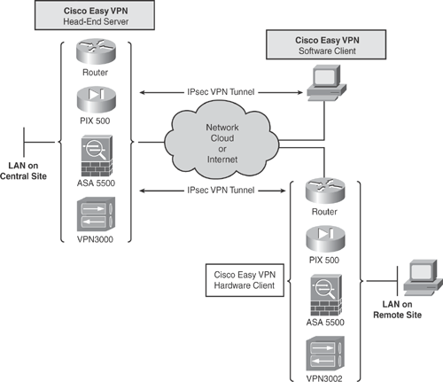
Easy VPN Software Client: This client is the traditional remote VPN implementation where remote mobile users terminate VPN connections directly to the head-end VPN server.
Easy VPN Hardware Client: With this client, a pseudo site-to-site VPN connection is established between two network devices emulating a LAN-to-LAN scenario. The remote end-user client behind the LAN is unaware of the VPN setup and does not require establishment of an individual VPN connection. Traffic flows encrypted between the VPN peers.
Figure 15-18 illustrates the two types of Easy VPN implementations.
There are two components in the Cisco Easy VPN implementation:
Cisco Easy VPN Server: Easy VPN Server acts as the VPN head-end device emulating a pseudo site-to-site VPN scenario, where the remote site devices are using the Cisco Easy VPN Remote client feature. The Easy VPN Server can be enabled and configured on Cisco IOS Routers (minimum Cisco IOS Software Release 12.2(8)T is required), Cisco PIX and ASA Security Appliances, and Cisco VPN 3000 Concentrators. Security policies are defined at the VPN head-end device and pushed to the remote VPN device when connected. See Figure 15-18.
Additionally, Easy VPN Server can act as the VPN head-end device terminating VPN tunnels initiated by mobile remote users that are using the Cisco VPN Client software. This flexibility allows mobile and remote workers to access any data and applications on the central site. See Figure 15-18.
Cisco Easy VPN Client (also referred to as Easy VPN Remote): The Cisco Easy VPN Remote Client feature allows a remote device to receive security policies from the head-end VPN server when the tunnel is established. The Easy VPN Remote client is easy to set up, with minimal configuration required at the remote client site.
Cisco Easy VPN Remote Software Client is available on Windows, Macintosh, Linux, and Solaris platforms.
The Cisco Easy VPN Remote Hardware Client is available on Cisco IOS Routers, Cisco PIX 501 and 506E, ASA Security Appliances, and Cisco VPN 3002 Hardware Clients. See Figure 15-18.
Tip
Refer to the following Cisco URL to download Cisco VPN software. Note that strong cryptographic encryption access is required to download Cisco VPN Software: http://www.cisco.com/kobayashi/sw-center/sw-vpn.shtml.
The Cisco Easy VPN Remote Client has the following three modes of operation:
Client Mode (also known as PAT mode): Specifies that Network Address Translation (NAT) or Port Address Translation (PAT) be employed to hide all devices behind the remote site from those on the server site. All traffic from the remote site hosts on the private network appears on the network site behind the server site with a single source IP address that is assigned to the IKE peer. This IP address is the one central server site that the VPN peer assigns to the remote site VPN peer. In client mode, traffic cannot be initiated from a host on the private network at the server site. The IPsec SA for this IP address is automatically created by the Easy VPN Remote Client device. This IP address is also commonly used for troubleshooting (by using ping, Telnet, and Secure Shell).
Network Extension Mode: Specifies that the hosts at the remote site of the Easy VPN tunnel should be given IP addresses that are fully routable and reachable by the central server site network over the IPsec tunnel. These IP addresses can either be on the same subnet as the server site network or on a separate subnet, assuming that the server site routers are configured to correctly route those subnets over the IPsec tunnel. PAT is not used in this scenario, thereby allowing the remote site hosts to have direct access to the hosts on the server network.
Network Extension Plus+ Mode: Is identical to the previous network extension mode, with the additional capability of being able to request an IP address via mode configuration.
All the previously described modes optionally support the Split-Tunnel feature. By default, all remote site client traffic is routed and tunneled through the VPN server. Split-tunneling allows you to control more granularly which specific hosts or subnets can traverse the IPsec tunnel. Networks and hosts defined in the Split-Tunnel ACL will be encrypted and sent via the tunnel, and all other traffic goes unencrypted in clear text (without applying IPsec) through the local egress interface based on the routing table. Example 15-4 shows how to configure split tunneling for specific subnets using an ACL.
Figure 15-19 illustrates a traditional hardware-based Cisco Easy VPN IPsec scenario that uses Cisco IOS Routers for both the client and the server.
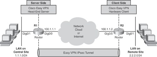
Based on Figure 15-19, Examples 15-4 and 15-5 show a traditional Cisco Easy VPN configuration on Cisco IOS Routers.
The server side configuration, hostname R1, in Example 15-4 shows the Extended Authentication (XAUTH) and Split-Tunnel features being used.
The client-side configuration, hostname R2, in Example 15-5 shows Network Extension mode being used.
|
Code View: hostname R1 ! ! Enable AAA for XAUTH aaa new-model aaa authentication login vpnauthen local aaa authorization network vpnauthor local ! ! Define Username credentials for XAUTH username cisco password cisco ! ! Define Phase 1 SA parameters crypto isakmp policy 10 encr 3des authentication pre-share group 2 ! crypto isakmp client configuration address-pool local vpnpool crypto isakmp xauth timeout 60 ! ! Define Easy VPN Remote Group Parameters & Split-Tunnel ACL# crypto isakmp client configuration group easyvpn key cisco123 dns 1.2.3.4 wins 1.2.3.4 domain cisco.com pool vpnpool acl 101 ! ! ! Define IPsec encryption and authentication algorithms crypto ipsec transform-set mytransformset esp-3des esp-sha-hmac ! ! Define Phase 2 SA parameters crypto dynamic-map mydynmap 10 set transform-set mytransformset reverse-route ! crypto map mydynmap client authentication list vpnauthen crypto map mydynmap isakmp authorization list vpnauthor crypto map mydynmap client configuration address respond crypto map cisco 10 ipsec-isakmp dynamic mydynmap ! ! ! Crypto map applied to outbound interface interface GigabitEthernet0/0 ip address 100.1.1.1 255.255.255.0 crypto map cisco ! ! Interface that is connected to the private side of the network for encryption interface GigabitEthernet0/1 ip address 1.1.1.1 255.255.255.0 ! ! Define IP pool for VPN connected Users ip local pool vpnpool 172.16.1.1 172.16.1.254 ip route 0.0.0.0 0.0.0.0 GigabitEthernet0/0 ! ! Define ACL for Split-Tunnel access-list 101 permit ip 1.1.1.0 0.0.0.255 any ! <..> |
|
Code View: hostname R2 <..> ! ! Define Easy VPN Remote Group Parameters crypto ipsec client ezvpn myeasyvpn connect auto group easyvpn key cisco123 mode network-extension peer 100.1.1.1 username cisco password cisco xauth userid mode local ! ! Define Easy VPN Outside Interface interface GigabitEthernet0/0 ip address 100.1.1.2 255.255.255.0 crypto ipsec client ezvpn myeasyvpn outside ! ! Define Easy VPN Inside Interface interface GigabitEthernet0/1 ip address 2.2.2.2 255.255.255.0 crypto ipsec client ezvpn myeasyvpn inside ! <..> |
Tip
Refer to the following Cisco technical documentation for additional Easy VPN configuration examples: http://www.cisco.com/en/US/products/ps6635/products_data_sheet09186a00801541d5.html#wp1067163.
Cisco introduced the Dynamic Virtual Tunnel Interface (VTI) method for scalable Remote Access IPsec-based VPN. DVTI is an enhanced method and can be used in Cisco Easy VPN Server and Remote Client implementations. As mentioned previously, the DVTI technology will replace the traditional dynamic crypto maps and the dynamic hub-and-spoke method for establishing tunnels. DVTI technology combined with Cisco Easy VPN will provide highly secure connectivity for Remote Access VPN.
One of the important characteristics of the DVTI is that it provides an on-demand unique virtual access interface for each remote VPN connection that is cloned from a virtual template configuration, which inherits the IPsec configuration and any other features configured on the virtual template interface, such as NAT, QoS, NetFlow, or ACLs. This allows the configuring of varying security policies for different remote access connections. DVTI with Easy VPN provides a routable interface for forwarding traffic based on IP routing tables.
Figure 15-20 illustrates the enhanced Cisco Easy VPN with IPsec DVTI scenario using Cisco IOS Routers for both client and server.
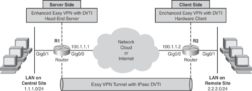
Based on Figure 15-20, Examples 15-6 and 15-7 show the enhanced Cisco Easy VPN with IPsec DVTI configuration method on Cisco IOS routers.
The server-side configuration, hostname R1, in Example 15-6 shows that ISAKMP profile, IPsec profile, Extended Authentication (XAUTH) and Split-Tunnel features are being used.
The client-side configuration in Example 15-7 shows client mode (PAT mode), hostname R2, is being used on the client router. With the enhancement in client mode operation, the dynamic IP address that is assigned to the client router from the server pool is automatically assigned to an available Loopback interface, and Easy VPN Remote Router automatically creates a corresponding IPsec SA for this IP address.
|
Code View: hostname R1 ! ! Enable AAA for XAUTH aaa new-model aaa authentication login default local aaa authorization network default local ! ip cef ! Define Username credentials for XAUTH username cisco privilege 15 password 0 cisco ! ! policy-map test123 class class-default shape average 1280000 ! ! ! Define Phase 1 SA parameters crypto isakmp policy 10 encr 3des authentication pre-share group 2 crypto isakmp key cisco123 address 0.0.0.0 0.0.0.0 crypto isakmp keepalive 10 ! ! Define Easy VPN Remote Group Parameters & Split-Tunnel ACL# crypto isakmp client configuration group cisco key cisco dns 1.2.3.4 wins 1.2.3.4 domain cisco.com pool dvtipool acl 101 ! ! Define ISAKMP profile and bind parameters crypto isakmp profile myisakmpprofile match identity group cisco isakmp authorization list default client configuration address respond virtual-template 1 ! ! ! Define IPsec encryption and authentication algorithms crypto ipsec transform-set mytransformset esp-3des esp-sha-hmac ! ! Define Phase 2 IPsec profile and bind parameters crypto ipsec profile myipsecprofile set transform-set mytransformset set isakmp-profile myisakmpprofile ! interface GigabitEthernet0/0 ip address 100.1.1.1 255.255.255.0 ! interface GigabitEthernet0/1 ip address 1.1.1.1 255.255.255.0 ! ! Define Virtual Template for DVTI cloning & apply IPsec profile interface Virtual-Template1 type tunnel ip unnumbered GigabitEthernet0/0 tunnel source GigabitEthernet0/0 tunnel mode ipsec ipv4 tunnel protection ipsec profile myipsecprofile service-policy output test123 ! ! Define IP pool for VPN connected Users ip local pool dvtipool 172.16.1.1 172.16.1.254 ip route 0.0.0.0 0.0.0.0 GigabitEthernet0/0 ! ! ! Define ACL for Split-Tunnel access-list 101 permit ip 1.1.1.0 0.0.0.255 any ! <..> |
|
Code View: hostname R2 ! no aaa new-model ! ip cef username cisco privilege 15 password 0 cisco ! policy-map test123 class class-default shape average 128000 ! crypto isakmp policy 10 encr 3des authentication pre-share group 2 ! crypto isakmp key cisco123 address 0.0.0.0 0.0.0.0 crypto isakmp keepalive 10 ! ! ! Define Easy VPN Remote Group Parameters crypto ipsec client ezvpn mydvtieasyvpn connect auto group cisco key cisco local-address GigabitEthernet0/0 mode client peer 100.1.1.1 username cisco password cisco xauth userid mode local ! ! ! Define Easy VPN Outside Interface interface GigabitEthernet0/0 ip address 100.1.1.2 255.255.255.0 ip virtual-reassembly crypto ipsec client ezvpn mydvtieasyvpn ! ! Define Easy VPN Inside Interface interface GigabitEthernet0/1 ip address 2.2.2.2 255.255.255.0 ip virtual-reassembly crypto ipsec client ezvpn mydvtieasyvpn inside ! ! Define Virtual Template for DVTI cloning interface Virtual-Template1 type tunnel no ip address ip virtual-reassembly tunnel mode ipsec ipv4 service-policy output test123 ! ip route 0.0.0.0 0.0.0.0 GigabitEthernet0/0 ! <..> |