VPN-based security solutions are increasingly popular and have proven to be an effective and secure technology for protecting sensitive data that is traversing insecure channel mediums, such as the Internet.
Traditional IPsec-based site-to-site, hub-to-spoke VPN deployment models do not scale well and are adequate only for small- and medium-sized networks. As demand for IPsec-based VPN implementation grows, organizations with large-scale enterprise networks require scalable and dynamic IPsec solutions that interconnect sites across the Internet with reduced latency, while optimizing network performance and bandwidth utilization.
The Dynamic Multipoint VPN (DMVPN) technology is used for scaling IPsec VPN networks by offering a large-scale IPsec VPN deployment model that allows the network to expand and realize its full potential. DMVPN offers scalability that enables zero-touch deployment models.
This chapter provides a complete overview of the DMVPN solution architecture, implementation, and various deployment scenarios.
DMVPN allows IPsec VPN networks to better scale hub-to-spoke and spoke-to-spoke designs, thereby optimizing performance and reducing latency for communications between sites.
DMVPN offers a wide range of benefits, including the following:
The capability to build dynamic hub-to-spoke and spoke-to-spoke IPsec tunnels
Optimized network performance
Reduced latency for real-time applications
Reduced router configuration on the hub that provides the capability to dynamically add multiple spoke tunnels without touching the hub configuration
Automatic triggering of IPsec encryption by virtue of GRE tunnel source and destination assuring zero packet loss
Support for spoke routers with dynamic physical interface IP addresses (for example, DSL and cable connections)
The capability to establish dynamic and direct spoke-to-spoke IPsec tunnels for communication between sites without having the traffic go through the hub; that is, intersite communication bypassing the hub
Support for dynamic routing protocols running over the DMVPN tunnels
Support for multicast traffic from hub to spokes
Support for VPN Routing and Forwarding (VRF) integration extended in multiprotocol label switching (MPLS) networks
Self-healing capability maximizing VPN tunnel uptime by rerouting around network link failures
Load-balancing capability offering increased performance by transparently terminating VPN connections to multiple head-end VPN devices
With networks becoming geographically distributed, network availability over a secure channel is becoming a critical factor in designing scalable IPsec VPN solution designs. DMVPN solution architecture is by far the most effective and scalable solution available.
DMVPN was introduced in multiple phases to address the various topological needs.
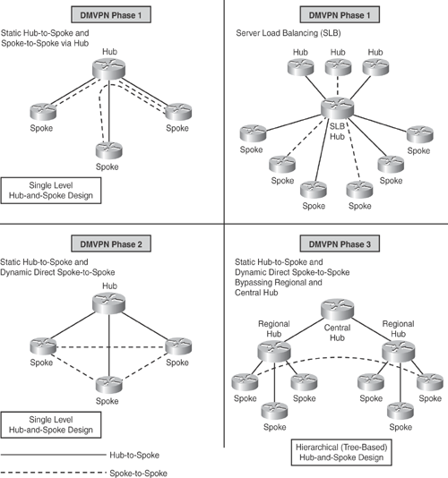
Phase 1—Hub-to-Spoke Designs: Phase 1 was the first design introduced for hub-to-spoke implementation, where spoke-to-spoke traffic would traverse via the hub. Phase 1 also introduced daisy chaining of identical hubs for scaling the network, thereby providing Server Load Balancing (SLB) capability to increase the CPU power.
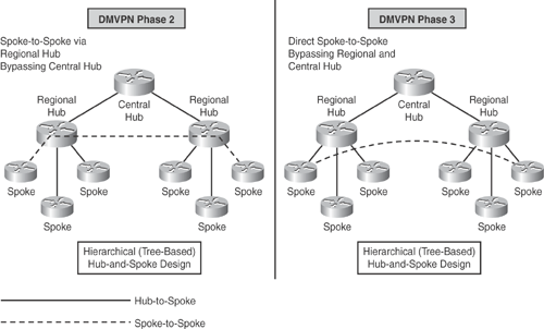
Phase 2—Spoke-to-Spoke Designs: Phase 2 design introduced the ability for dynamic spoke-to-spoke tunnels without having the traffic go through the hub; that is, intersite communication bypassing the hub, thereby providing greater scalability and better control of traffic. In Phase 2 network design, each DMVPN network is independent of other DMVPN networks, causing spoke-to-spoke traffic from different regions to traverse through the regional hubs without the need to go through the central hub. Figure 16-1 illustrates this scenario.

Phase 3—Hierarchical (Tree-Based) Designs: Phase 3 extended Phase 2 design with the capability to establish dynamic and direct spoke-to-spoke tunnels from different DMVPN network across multiple regions. In Phase 3, all regional DMVPN networks are bound together to form a single hierarchical (tree-based) DMVPN network, including the central hubs. Spoke-to-spoke traffic from different regions can establish direct tunnels with each other, thereby bypassing both the regional and central hubs, as illustrated in Figure 16-2.

Figure 16-1 depicts the DMVPN phases illustrating the various network designs that can be implemented.
Figure 16-2 illustrates how spoke-to-spoke traffic flow in a hierarchical DMVPN (tree-based) design differs between Phase 2 and Phase 3 implementations. Before Phase 3, spoke-to-spoke tunnels were established through regional hubs. In Phase 3, spoke-to-spoke tunnels are established directly with each other, bypassing both the regional and central hubs.
The DMVPN solution is a combination of several protocols and relies on the following Cisco-enhanced standard technologies. The major functional components include the following:
Generic Routing Encapsulation (GRE) Protocol: A tunneling protocol developed by Cisco, which is designed to encapsulate IP unicast, multicast, and broadcast packets. GRE uses IP protocol number 47.
Next Hop Resolution Protocol (NHRP): A Layer 2 client-server resolution protocol used to map a tunnel IP address to an NBMA address. NHRP functions in a manner similar to ARP or Reverse ARP (Frame Relay). Like ARP, NHRP can have static or dynamic mappings. The hub router maintains an NHRP database of the public interface addresses for each spoke. When the spoke boots, it registers its real address with the hub and queries the NHRP database for real addresses of the destinations of other spokes so that it can build direct tunnels.
Dynamic Routing Protocol: A protocol used to advertise private networks within the DMVPN networks. IP routing updates and IP multicast data packets traverse only hub-and-spoke tunnels. Unicast IP data packets traverse both hub-and-spoke and direct dynamic spoke-to-spoke tunnels. Routing adjacencies are established across the hub-to-spoke links, and the spoke-to-spoke routing logic is performed by NHRP. Routing protocol does not monitor the state of spoke-to-spoke tunnels. Protocols that are supported include RIP, EIGRP, OSPF, ODR, and BGP.
Standards-based IPsec Encryption Protocols: Protocols used to protect tunnels in the DMVPN solution.
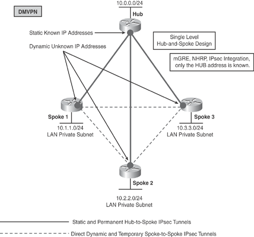
DMVPN builds a dynamic tunnel overlay network. With the aid of Figure 16-3, the following points explain how DMVPN works:
Initially each spoke establishes a permanent IPsec tunnel to the hub. (At this stage, spokes do not establish tunnels with other spokes within the network.) The hub address should be static and known by all of the spokes.
Each spoke registers its real address as a client to the NHRP server on the hub. The NHRP server maintains an NHRP database of the public interface addresses for each spoke.
When a spoke requires that packets be sent to a destination (private) subnet on another spoke, it queries the NHRP server for the real (outside) addresses of the other spoke's destination so that it can build direct tunnels.
The NHRP server looks up the NHRP database for the corresponding destination spoke and replies with the real address for the target router. The use of NHRP prevents the need of dynamic routing protocols to discover the route to the correct spoke. (Dynamic routing adjacencies are established only from spoke to hub.)
After the originating spoke learns the peer address of the target spoke, it initiates a dynamic IPsec tunnel to the target spoke.
With the integration of the multipoint GRE (mGRE) interface, NHRP, and IPsec, a direct dynamic spoke-to-spoke tunnel is established over the DMVPN network.

The spoke-to-spoke tunnels are established on demand whenever traffic is sent between the spokes. Thereafter, packets can bypass the hub and use the spoke-to-spoke tunnel directly. Refer to Figure 16-3 to better understand how this feature works.
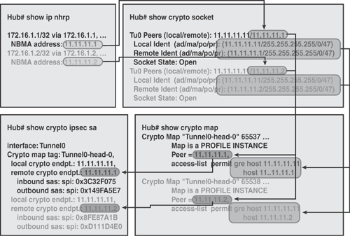
The following is a list of DMVPN data structures and how the interaction works to form a complete framework, as illustrated in Figure 16-4:
NHRP Mapping Table: The mapping of VPN and tunnel IP addresses to NBMA address (physical address). Use the show ip nhrp command to view the mapping, as shown in Figure 16-4.
Crypto Socket Table: The mapping between NHRP and IPsec, as shown in Figure 16-4. The show crypto socket and show crypto ipsec profile commands can be used to display this information.
Crypto Map Table: The dynamic crypto map entry for each multipoint GRE tunnel or for each IPsec profile. The show crypto map command can be used to display this information.
ISAKMP and IPsec SA Table: The table that shows the ISAKMP Phase 1 SA and Phase 2 IPsec SA information. The show crypto session, show crypto isakmp sa, and the show crypto ipsec sa commands can be used to display this information.
