Multiprotocol Label Switching (MPLS) is a widely used transport mechanism that carries data traffic over a packet-switched network (PSN).
MPLS VPN is a service solution extension of the MPLS for providing VPN services that allows enterprises and service providers to build highly efficient, scalable, and secure next-generation intelligent networks.
This chapter provides an overview of MPLS VPN architecture and a basic understanding of the various types of MPLS VPNs. The chapter also covers the Cisco Layer 2 VPN (L2VPN) and Layer 3 VPN (L3VPN) solutions.
MPLS is a transport mechanism that carries data over a packet-switched network. MPLS is widely used by service providers and large-scale enterprise networks.
MPLS framework was designed to provide flexibility to operate with virtually any Layer 3 and Layer 2 technology. MPLS-based solutions can be integrated seamlessly over any existing infrastructure.
MPLS supports several Layer 3 and Layer 2 protocols. Table 19-1 shows a list of commonly supported protocols.
| OSI Layer 3 | OSI Layer 2 | |
|---|---|---|
| MPLS can be used to carry different types of traffic | Supports IPv4, IPv6, IPX, and AppleTalk at Layer 3 | Supports Ethernet, Frame Relay, PPP, Token Ring, FDDI, SONET, and ATM at Layer 2 |
MPLS was originally a Cisco proprietary technology called tag switching—a solution designed by a group of Cisco engineers. It was later handed over to the IETF for open standardization and was renamed label switching.
Tip
MPLS working documents, Internet-draft papers, and RFCs can be downloaded from the following Internet Engineering Task Force (IETF)–based MPLS working group website:
The MPLS architecture defines the basic mechanism for performing label switching within an MPLS core network.
MPLS combines the benefits of packet forwarding based on connection-oriented Layer 2 switching with connectionless Layer 3 routing.
The advantage of this architecture is that routers at the network edge can use conventional IP forwarding, whereas routers in the network core can run MPLS and use switching instead of conventional routing table lookup. This also simplifies the hop-by-hop data forwarding path by replacing the Layer 3 route lookup function performed in traditional routers with a label swapping mechanism, thus providing faster packet forwarding and improved network performance.
MPLS architecture assigns labels to each packet to be able to transport them across the MPLS core network. The concept of label is similar to other Layer 2 technologies, such as Frame Relay or ATM. Labels are used to perform the next-hop label lookup at Layer 2 to traverse the network. Each node within the network processes the label on the incoming packet, swaps the label with a new label at outgoing (label swapping), and forwards the packet to the next node.
The new advanced label-swapping technique in MPLS improves the network performance and provides greater scalability and flexibility in the delivery of routing services.
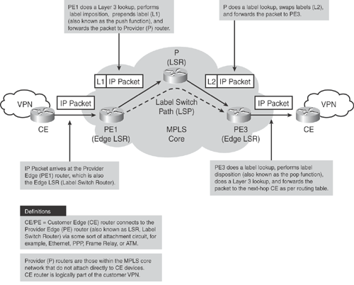
Figure 19-1 illustrates the MPLS core architecture.

When a packet arrives on the ingress Label Switch Router (LSR), also called the Provider Edge (PE) router, the PE router assigns a label to transport the packet through the MPLS network.
As shown in Figure 19-2, each LSR performs a specific function; for example, the LSR at the edge performs either label imposition (also known as the push functions) or label removing (also known as the pop function). Other LSRs in the path simply swap the labels.

Each LSR maintains a Label Forwarding Information Base (LFIB) table that is built using the IP routing table to determine the label binding exchange. The LFIB provides an incoming labeled packet with the outgoing interface and the new label information associated respectively with the outgoing packet.
Adjacent nodes perform a label binding exchange for individual subnets (destination-based IP routing) using the Cisco proprietary Tag Distribution Protocol (TDP) or the IETF-standard Label Distribution Protocol (LDP). If the route (prefix/mask and next hop) learned via the TDP/LDP matches the route learned via IGP in the routing table, an entry is created in the LFIB on the LSR.
Packets in the MPLS core are forwarded based on the labels that are prepended by the LSR, and not based on the IP destination address.
The LSR-to-LSR journey of this packet within the MPLS core crosses several LSR routers; this path is called the Label Switched Path (LSP). LSP is essentially a set of LSRs (similar to the AS path in BGP) through which a labeled packet must traverse to reach the edge LSR. As a packet traverses the LSP, each LSR swaps the label until it reaches the router before the last LSR (the penultimate hop), which pops the label and transmits the packet without the label to the last hop egress LSR, where the packet is out of the MPLS core and forwarded to the destination CE.
Figure 19-2 shows a detailed diagram demonstrating how the packet forwarding and label swapping works within the MPLS core network.
MPLS VPN and IPsec VPN are complementary technologies; both have their benefits, though in different implementations.
The MPLS VPN solution provides a pseudo point-to-point connection that allows networks to peer indirectly, providing a sense of security and data privacy. MPLS VPN creates a private data path through the MPLS core network, providing faster and more secure data paths without network overhead.
MPLS VPN does not provide data confidentiality or cryptography functions. This means that data could possibly be intercepted during transmission without sender/receiver knowledge. Thus, it will often not meet requirements for confidentiality or nonrepudiation that may be required by some of the industry standards (for example, HIPAA). The security must be provided at the network layer. To provide data confidentiality, IPsec VPN solution at the network layer can be deployed as an overlay over the MPLS network.
Table 19-2 shows a comparison between MPLS VPN and IPsec VPN technologies.
| MPLS VPN | IPsec VPN | |
|---|---|---|
| Placement | Implemented in core network (resides in service provider network). | Implemented at local loop, edge, and off-net (resides in customer network). |
| Scalability | Highly scalable because no site-to-site peering is required. Can support tens of thousands of VPN connections over the same network. | Scalability becomes a challenge when implementing large-scale, fully meshed IPsec VPN solutions. Requires careful planning and coordination for key management, distribution, peering configuration, and more. |
| Provisioning | To enable MPLS VPN connection, a one-time provisioning is required to install customer's edge (CE) and provider's edge (PE) routers to join the MPLS core. | IPsec VPN uses the IP core network provisioning, offering services with reduced operation expense through centralized network-level infrastructure. Customer edge local equipment is used to deploy IPsec end-to-end solution. |
| Deployment | Provider dependency, because it requires MPLS-capable network infrastructure at the core and edge of the provider network. | Does not depend on the provider and can be deployed across any existing IP network. |
| Authentication | Connections are authenticated via logical VPN membership during provisioning, based on logical port and unique route descriptor. Unauthorized access is denied. | Connections are authenticated via digital certificate or preshared keys. Packets that do not conform to the security policy are dropped. |
| Confidentiality | Logical point-to-point circuits are separated, providing a sense of security and data privacy. | Set of standard encryption and tunneling mechanisms are used at the IP network layer to protect data. |
| Quality of Service (QoS) and Service Level Agreement (SLA) | Provides QoS and SLAs with robust traffic-engineering capabilities. | Does not directly address QoS and SLAs, although Cisco IPsec solutions can preserve packet classification for QoS within an IPsec tunnel. |
| VPN client | MPLS VPN is a network-based service; hence, end users do not require VPN client software to communicate with remote networks. | Required only for Remote Access VPN solution. Cisco VPN client software is available for various platforms, including Microsoft, Linux, and MAC OS. For site-to-site network-based IPsec deployments, VPN client is not required. |
| Note: The information in Table 19-2 is compiled from the Cisco white paper on "VPN Architectures - Comparing MPLS and IPsec" at http://www.cisco.com/en/US/netsol/ns590/networking_solutions_white_paper09186a008009d67f.shtml. | ||
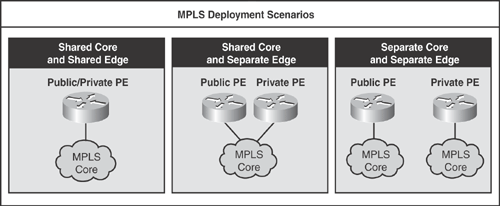
There are three basic deployment scenarios for implementing MPLS solutions, as shown in Figure 19-3.
Shared Core and Shared Edge: This design comprises a single MPLS core that services both the public IP and private VPN traffic. Similarly at the edge, a single PE router is used to terminate both public IP and private VPN connections.
Shared Core and Separate Edge: This design also comprises a single MPLS core that services both the public IP and private VPN traffic. At the edge, dedicated, purpose-built PE routers are used to terminate public IP and private VPN connections, respectively.
Separate Core and Separate Edge: This design comprises separate MPLS cores for each public IP and private VPN traffic connections, respectively. Similarly at the edge, dedicated PE routers (purpose-built) are used to terminate public IP and private VPN connections, respectively.

Note
The information in Figure 19-3 is compiled from the Cisco Networkers session presentation# SEC-2100 – "MPLS-VPN Security Guidelines."
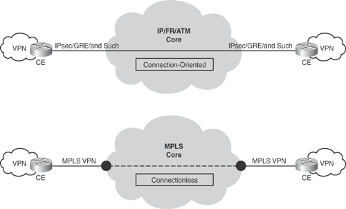
VPN technologies vary, and there is no fixed classification for VPN solutions. VPN can be categorized in two ways: connection-oriented and connectionless VPN. As shown in Figure 19-4, connection-oriented VPN has an end-to-end path through the core network. Examples include IPsec and generic routing encapsulation (GRE).

Connectionless VPN does not have a direct relationship with a peer site and has a virtual path joining two sites via the core network. Examples include MPLS VPN, which connects two customer sites via the MPLS core cloud.
Connectionless VPNs scale better because less information is kept at the customer edge, whereas with connection-oriented VPNs, all information is kept at the edge. Figure 19-4 illustrates the connection-oriented and connectionless VPN technologies.