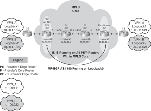
Figure 19-6 topology demonstrates a basic L3VPN scenario using MP-BGP. The MPLS core interconnects VPN sites as shown in Figure 19-6. The customer CE router is a member of two VPNs (VPN_A and VPN_B) on each site with overlapping subnets. Intermediate System-to-Intermediate System (IS-IS) protocol is running within the MPLS core network.

Based on the Figure 19-6 illustration, the following configuration examples provide deployment guidelines for implementing basic MPLS L3VPN solutions.
Example 19-1 shows PE-1 configuration
Example 19-2 shows PE-2 configuration
Example 19-3 shows P-1 configuration
Example 19-4 shows P-2 configuration
|
Code View: hostname PE1 ! ip cef ! !--- VPN A commands. ! ip vrf VPN_A !--- Enables the VPN routing and forwarding (VRF) routing table. ! rd 100:111 !--- Route distinguisher creates routing and forwarding tables for a VRF. route-target export 100:111 route-target import 100:111 !--- Creates lists of import and export route-target extended. communities for the specified VRF. ! ! ! !--- VPN B commands. ! ip vrf VPN_B rd 100:222 route-target export 100:222 route-target import 100:222 ! interface Loopback0 ip address 10.10.10.1 255.255.255.255 ip router isis ! !--- VPN A commands. ! interface Looback1 ip vrf forwarding VPN_A !--- Associates a VRF instance with an interface or subinterface. ip address 100.0.1.1 255.255.255.0 !--- Looback1 and Loopback2 use the same IP address 100.0.1.1 !--- Duplicate subnets are allowed because they belong to two different VRF no ip directed-broadcast ! ! ! !--- VPN B commands. ! interface Looback2 ip vrf forwarding VPN_B ip address 100.0.1.1 255.255.255.0 !--- Looback1 and Loopback2 use the same IP address 100.0.1.1 !--- Duplicate subnets are allowed because they belong to two different VRF no ip directed-broadcast ! interface Serial2/0 no ip address no ip directed-broadcast encapsulation frame-relay no fair-queue ! interface Serial2/0.1 point-to-point description link to P1 bandwidth 512 ip address 10.1.1.1 255.255.255.252 no ip directed-broadcast ip router isis tag-switching ip frame-relay interface-dlci 101 ! router isis net 49.0001.0000.0000.0004.00 is-type level-1 ! router bgp 100 bgp log-neighbor-changes neighbor 10.10.10.2 remote-as 100 neighbor 10.10.10.2 update-source Loopback0 ! ! !--- VPN A and B commands address-family vpnv4 neighbor 10.10.10.2 activate neighbor 10.10.10.2 send-community both exit-address-family ! ! ! !--- VPN A commands address-family ipv4 vrf VPN_A redistribute connected no auto-summary no synchronization exit-address-family ! ! ! !--- VPN B commands address-family ipv4 vrf VPN_B redistribute connected no auto-summary no synchronization exit-address-family ! ! ! ip classless ! end |
|
Code View: hostname PE2 ! ip cef ! !--- VPN A commands ! ip vrf VPN_A rd 100:111 route-target export 100:111 route-target import 100:111 ! !--- VPN B commands. ! ip vrf VPN_B rd 100:222 route-target export 100:222 route-target import 100:222 ! interface Loopback0 ip address 10.10.10.2 255.255.255.255 ip router isis ! !--- VPN A commands ! interface Looback1 ip vrf forwarding VPN_A ip address 100.0.2.1 255.255.255.0 !--- Looback1 and Loopback2 use the same IP address 100.0.2.1 !--- Duplicate subnets are allowed because they belong to two different VRF ! ! !--- VPN B commands ! interface Looback2 ip vrf forwarding VPN_B ip address 100.0.2.1 255.255.255.0 !--- Looback1 and Loopback2 use the same IP address 100.0.2.1 !--- Duplicate subnets are allowed because they belong to two different VRF ! ! interface Serial0/0 no ip address encapsulation frame-relay no ip mroute-cache ! interface Serial0/0.1 point-to-point description link to P2 bandwidth 512 ip address 10.1.1.10 255.255.255.252 ip router isis tag-switching ip frame-relay interface-dlci 403 ! router isis net 49.0001.0000.0000.0006.00 is-type level-1 ! router bgp 100 neighbor 10.10.10.1 remote-as 100 neighbor 10.10.10.1 update-source Loopback0 ! ! ! !--- VPN A and B commands ! address-family vpnv4 neighbor 10.10.10.1 activate neighbor 10.10.10.1 send-community both exit-address-family ! ! !--- VPN A commands ! address-family ipv4 vrf VPN_A redistribute connected no auto-summary no synchronization exit-address-family ! ! !--- VPN B commands ! address-family ipv4 vrf VPN_B redistribute connected no auto-summary no synchronization exit-address-family ! ! ip classless ! end |
|
Code View: hostname P1 ! ip cef ! interface Loopback0 ip address 10.10.10.3 255.255.255.255 ip router isis ! interface Serial0/0 no ip address encapsulation frame-relay no ip mroute-cache tag-switching ip no fair-queue ! interface Serial0/0.1 point-to-point description link to PE1 bandwidth 512 ip address 10.1.1.2 255.255.255.252 ip router isis tag-switching ip frame-relay interface-dlci 201 ! interface Serial0/0.2 point-to-point description link to P2 bandwith 512 ip address 10.1.1.5 255.255.255.252 ip router isis tag-switching ip frame-relay interface-dlci 203 ! router isis net 49.0001.0000.0000.0001.00 is-type level-1 ! ip classless ! end |
|
Code View: hostname P2 ! ip cef ! interface Loopback0 ip address 10.10.10.3 255.255.255.255 ip router isis ! interface Serial0/0 no ip address no ip directed-broadcast encapsulation frame-relay random-detect ! interface Serial0/0.1 point-to-point description link to PE2 ip address 10.1.1.9 255.255.255.252 no ip directed-broadcast ip router isis tag-switching ip frame-relay interface-dlci 304 ! interface Serial0/0.2 point-to-point description link to P1 ip address 10.1.1.6 255.255.255.252 no ip directed-broadcast ip router isis tag-switching ip frame-relay interface-dlci 302 ! router isis net 49.0001.0000.0000.0003.00 is-type level-1 ! ip classless ! end |
Tip
For more configuration examples on MPLS VPN, refer to following Cisco documentation URL: http://www.cisco.com/en/US/tech/tk436/tk428/tech_configuration_examples_list.html.
Note
IETF L3VPN is a working group responsible for standardization of Layer 3 VPN architectures, such as MPLS IP VPN, IP VPN using virtual routers, and IPsec VPN. More details can be found at http://www.ietf.org/html.charters/l3vpn-charter.html.