There are a number of variations in L2VPN designs and deployments, and several different technologies are available that can be used depending on different Layer 2 services. The technologies include Ethernet VLAN, Frame Relay PVC, ATM VC, HDLC, and PPP transport over a packet-based infrastructure across a service provider IP/MPLS cloud. The following sections provide some basic examples of Layer 2 service implementations, i.e., Ethernet VLAN over MPLS using VPWS- and VPLS-based architecture.
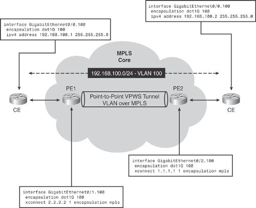
Figure 19-8 topology demonstrates basic VPWS (Virtual Private Wire Service) L2VPN point-to-point scenario transporting Ethernet VLAN over MPLS.

As shown in Figure 19-8, the MPLS core interconnects customer Ethernet between two sites over the MPLS core. The customer CE router on each site is configured on the same Layer 3 subnet 192.168.100.0/24, thereby establishing a virtual Layer 2 (VLAN) connection over the MPLS core network.
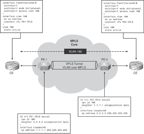
Figure 19-9 topology demonstrates a basic VPLS (Virtual Private LAN Service) L2VPN scenario transporting Ethernet VLAN over MPLS.

The MPLS core interconnects customer Ethernet VLAN between two sites, thereby establishing a virtual Layer 2 (VLAN) connection over the MPLS core network.