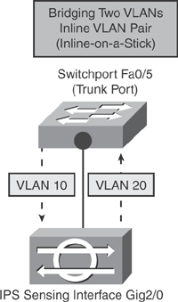
Based on Figure 20-11, Example 20-1 shows a basic configuration example that enables an inline VLAN pair mode on the sensor appliance. The inline VLAN pair is assigned to the default virtual sensor vs0. IPS interface GigabitEthernet2/0 connected to Switchport FastEthernet0/5 is being used for sensing in this example. The sensor performs VLAN bridging between pairs of VLANs on the trunk port. Traffic incoming to the sensor on VLAN 10 is inspected and sent out with VLAN TAG of VLAN 20 on the same physical interface (hair-pinning).

The sample configuration also shows some basic IPS initializing parameters such as configuring the hostname, IP address, default gateway, and access list to allow trusted hosts.
|
Code View: IPS# show configuration
! ------------------------------
! Current configuration last modified Mon Jul 09 11:16:02 2007
! ------------------------------
! Version 6.0(1)
! Host:
! Realm Keys key1.0
! Signature Definition:
! Signature Update S263.0 2006-12-18
! Virus Update V1.2 2005-11-24
! ------------------------------
service interface
physical-interfaces GigabitEthernet2/0
admin-state enabled
subinterface-type inline-vlan-pair
subinterface 1
vlan1 10
vlan2 20
<..>
service analysis-engine
virtual-sensor vs0
physical-interface GigabitEthernet2/0 subinterface-number 1
<..>
! ------------------------------
service host
network-settings
host-ip 172.16.10.1/24,172.16.10.254
host-name IPS
telnet-option disabled
access-list 172.16.10.0/24
<..>
! ------------------------------
|
Based on Figure 20-11, Example 20-2 shows the basic Switch Trunk port configuration that completes the inline VLAN pair setup, allowing VLAN 10 and VLAN 20 accordingly.
Switch# show run interface FastEthernet0/5
Building configuration...
Current configuration : 132 bytes
!
interface FastEthernet0/5
 switchport trunk encapsulation dot1q
 switchport trunk allowed vlan 10,20
 switchport mode trunk
end |
Example 20-3 shows a sample output from the IPS sensor appliance to verify interface configuration. Note that the interface function is "sensing" and the Inline mode is an inline-vlan-pair, which indicates that this is an inline VLAN pair mode setup.
|
Code View: IPS# show interfaces GigabitEthernet2/0
MAC statistics from interface GigabitEthernet2/0
Statistics From Subinterface 1
Statistics From Vlan 10
Total Packets Received On This Vlan = 759061
Total Bytes Received On This Vlan = 69709354
Total Packets Transmitted On This Vlan = 292105
Total Bytes Transmitted On This Vlan = 35889784
Statistics From Vlan 20
Total Packets Received On This Vlan = 292232
Total Bytes Received On This Vlan = 35897912
Total Packets Transmitted On This Vlan = 758907
Total Bytes Transmitted On This Vlan = 69699312
Interface function = Sensing interface
Description =
Media Type = TX
Default Vlan = 0
Inline Mode = Inline-vlan-pair
Pair Status = N/A
Hardware Bypass Capable = Yes when paired with GigabitEthernet2/1
Hardware Bypass Paired = No
Link Status = Up
Link Speed = N/A
Link Duplex = N/A
Missed Packet Percentage = 0
Total Packets Received = 1191064
Total Bytes Received = 118989462
Total Multicast Packets Received = 0
Total Broadcast Packets Received = 0
Total Jumbo Packets Received = 0
Total Undersize Packets Received = 0
Total Receive Errors = 0
Total Receive FIFO Overruns = 0
Total Packets Transmitted = 1051012
Total Bytes Transmitted = 105589096
Total Multicast Packets Transmitted = 0
Total Broadcast Packets Transmitted = 0
Total Jumbo Packets Transmitted = 0
Total Undersize Packets Transmitted = 0
Total Transmit Errors = 0
Total Transmit FIFO Overruns = 0
Dropped Packets From Vlans Not Mapped To Subinterfaces = 139771
Dropped Bytes From Vlans Not Mapped To Subinterfaces = 13382196
|