In a dynamic mesh spoke-to-spoke DMVPN design (also known as Phase 2 DMVPN design, as shown in Figure 16-1), a single mGRE interface is required on both the hub and the spoke routers. Dynamically addressed spokes are supported through the use of the NHRP registration process. When new spokes are added, no changes are required on the hub configuration. The main aspect of this design is that spoke-to-spoke traffic will traverse directly to another spoke (by forming Cisco Express Forwarding (CEF) adjacency), thereby bypassing the hub and reducing latency and load on the hub.
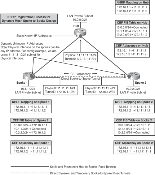
Figure 16-8 shows how the NHRP registration process works in a dynamic spoke-to-spoke DMVPN design. Spokes register their real addresses to the hub by using the NHRP registration process. When a spoke needs to send traffic to a destination (private) subnet on another spoke, it queries the NHRP server for the real (outside) addresses of the other spoke's destination so that it can build direct tunnels.

The NHRP server hub router looks up the NHRP database for the corresponding destination spoke and replies with the real address for the target router. After the originating spoke learns the peer address, it updates its NHRP mapping table for the destination spoke, and the corresponding CEF FIB table entries are created for the neighbor's private subnets. With this information, the spoke is able to build direct CEF adjacency with the target spoke and initiate a dynamic IPsec tunnel with the target spoke.
The spoke-to-spoke tunnels are established on demand whenever traffic is sent between the spokes. Thereafter, packets can bypass the hub and use the spoke-to-spoke tunnel directly, as shown in Figure 16-8.
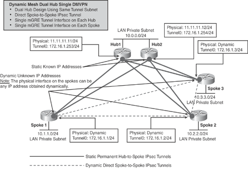
Based on the understanding of how NHRP registration and CEF adjacency work in a dynamic mesh design, Figure 16-9 illustrates the dual hub topology. Example 16-7 (Hub1), Example 16-8 (Hub2), Example 16-9 (Spoke1), and Example 16-10 (Spoke2) show the basic configuration examples using OSPF implementing the dual hub DMVPN topology scenario in a dynamic spoke-to-spoke design.

|
Code View: hostname Hub1 <..> ! Define Phase 1 SA parameters crypto isakmp policy 10 encr 3des authentication pre-share group 2 crypto isakmp key dmvpnkey address 0.0.0.0 0.0.0.0 ! ! Define IPsec encryption and authentication algorithms crypto ipsec transform-set mytran esp-3des esp-sha-hmac ! ! Define Phase 2 Parameters - IPsec Profile (set peer & match ACL not required) crypto ipsec profile vpnprof set transform-set mytran ! ! Interface that is connected to the private side of the network for encryption interface Loopback0 ! description LAN Private Subnet ip address 10.0.0.1 255.255.255.0 ! interface Tunnel0 ! description DMVPN HUB1 Router bandwidth 1000 ! Define Tunnel IP address ip address 172.16.1.253 255.255.255.0 ip mtu 1400 ! Define NHRP Server settings ip nhrp authentication cisco ip nhrp map multicast dynamic ip nhrp map 172.16.1.254 11.11.11.12 ip nhrp map multicast 11.11.11.12 ip nhrp network-id 123 ip nhrp holdtime 360 ! Define OSPF Parameters ip ospf network broadcast ip ospf cost 100 ip ospf priority 2 delay 1000 ip tcp adjust-mss 1360 tunnel source GigabitEthernet0/0 ! Define Multipoint GRE Type interface tunnel mode gre multipoint ! Define Tunnel key to Secure GRE interface tunnel key 12345 ! Apply IPsec profile Tunnel Protection tunnel protection ipsec profile vpnprof ! ! Egress interface with known static IP (No ACL or Crypto map) interface GigabitEthernet0/0 ip address 11.11.11.11 255.255.255.0 <..> ! Define Dynamic Routing Protocol to advertise PRIVATE Subnets via Tunnel router ospf 1 log-adjacency-changes network 10.0.0.0 0.255.255.255 area 0 network 172.16.1.0 0.0.0.255 area 0 ! <..> |
|
Code View: hostname Hub2 <..> ! Define Phase 1 SA parameters crypto isakmp policy 10 encr 3des authentication pre-share group 2 crypto isakmp key dmvpnkey address 0.0.0.0 0.0.0.0 ! ! Define IPsec encryption and authentication algorithms crypto ipsec transform-set mytran esp-3des esp-sha-hmac ! ! Define Phase 2 Parameters - IPsec Profile (set peer & match ACL not required) crypto ipsec profile vpnprof set transform-set mytran ! ! Interface that is connected to the private side of the network for encryption interface Loopback0 ! description LAN Private Subnet ip address 10.0.0.2 255.255.255.0 ! interface Tunnel0 ! description DMVPN HUB2 Router bandwidth 1000 ! Define Tunnel IP address ip address 172.16.1.254 255.255.255.0 ip mtu 1400 ! Define NHRP Server settings ip nhrp authentication cisco ip nhrp map multicast dynamic ip nhrp map 172.16.1.253 11.11.11.11 ip nhrp map multicast 11.11.11.11 ip nhrp network-id 123 ip nhrp holdtime 360 ! Define OSPF Parameters ip ospf network broadcast ip ospf cost 105 ip ospf priority 2 delay 1000 ip tcp adjust-mss 1360 tunnel source GigabitEthernet0/0 ! Define Multipoint GRE Type interface tunnel mode gre multipoint ! Define Tunnel key to Secure GRE interface tunnel key 12345 ! Apply IPsec profile Tunnel Protection tunnel protection ipsec profile vpnprof ! ! Egress interface with known static IP (No ACL or Crypto map) interface GigabitEthernet0/0 ip address 11.11.11.12 255.255.255.0 <..> ! Define Dynamic Routing Protocol to advertise PRIVATE Subnets via Tunnel router ospf 1 log-adjacency-changes network 10.0.0.0 0.255.255.255 area 0 network 172.16.1.0 0.0.0.255 area 0 ! <..> |
|
Code View: hostname Spoke1 <..> ! Define Phase 1 SA parameters crypto isakmp policy 10 encr 3des authentication pre-share group 2 crypto isakmp key dmvpnkey address 0.0.0.0 0.0.0.0 ! ! Define IPsec encryption and authentication algorithms crypto ipsec transform-set mytran esp-3des esp-sha-hmac ! ! Define Phase 2 Parameters - IPsec Profile (set peer & match ACL not required) crypto ipsec profile vpnprof set transform-set mytran ! ! Interface that is connected to the private side of the network for encryption interface Loopback0 ! description LAN Private Subnet ip address 10.1.1.1 255.255.255.0 ! interface Tunnel0 __________________________ ! description DMVPN Spoke1 bandwidth 1000 ! Define Tunnel IP address ip address 172.16.1.1 255.255.255.0 ip mtu 1400 ! Define NHRP Spoke settings with Static Mapping ip nhrp authentication cisco ! Define NHRP Hub1 Mapping ip nhrp map multicast 11.11.11.11 ip nhrp map 172.16.1.253 11.11.11.11 ! Define NHRP Hub2 Mapping ip nhrp map multicast 11.11.11.12 ip nhrp map 172.16.1.254 11.11.11.12 ! Network ID must match with Server ip nhrp network-id 123 ip nhrp holdtime 360 ! Define IP address for both Hubs ip nhrp nhs 172.16.1.253 ip nhrp nhs 172.16.1.254 delay 1000 ip tcp adjust-mss 1360 ! Define OSPF Parameters ip ospf network broadcast ip ospf priority 0 tunnel source FastEthernet0/0 ! Define Multipoint GRE Type interface tunnel mode gre multipoint ! Define Tunnel key to Secure GRE interface tunnel key 12345 !Apply IPsec profile Tunnel Protection tunnel protection ipsec profile vpnprof ! ! Egress interface with unknown IP (No ACL or Crypto map). In this example, we are statically defining IP, but this can be dynamically obtained interface FastEthernet0/0 ip address 11.11.11.1 255.255.255.0 ! <..> ! Define Dynamic Routing Protocol to advertise PRIVATE Subnets via Tunnel router ospf 1 log-adjacency-changes network 10.0.0.0 0.255.255.255 area 0 network 172.16.1.0 0.0.0.255 area 0 ! <..> |
|
Code View: hostname Spoke2 <..> ! Define Phase 1 SA parameters crypto isakmp policy 10 encr 3des authentication pre-share group 2 crypto isakmp key dmvpnkey address 0.0.0.0 0.0.0.0 ! ! Define IPsec encryption and authentication algorithms crypto ipsec transform-set mytran esp-3des esp-sha-hmac ! ! Define Phase 2 Parameters - IPsec Profile (set peer & match ACL not required) crypto ipsec profile vpnprof set transform-set mytran ! ! Interface that is connected to the private side of the network for encryption interface Loopback0 ! description LAN Private Subnet ip address 10.2.2.2 255.255.255.0 ! interface Tunnel0 ! description DMVPN Spoke2 bandwidth 1000 ! Define Tunnel IP address ip address 172.16.1.2 255.255.255.0 ip mtu 1400 ! Define NHRP Spoke settings with Static Mapping ip nhrp authentication cisco ! Define NHRP Hub1 Mapping ip nhrp map multicast 11.11.11.11 ip nhrp map 172.16.1.253 11.11.11.11 ! Define NHRP Hub2 Mapping ip nhrp map multicast 11.11.11.12 ip nhrp map 172.16.1.254 11.11.11.12 ! Network ID must match with Server ip nhrp network-id 123 ip nhrp holdtime 360 ! Define IP address for both Hubs ip nhrp nhs 172.16.1.253 ip nhrp nhs 172.16.1.254 delay 1000 ip tcp adjust-mss 1360 ! Define OSPF Parameters ip ospf network broadcast ip ospf priority 0 tunnel source FastEthernet0/0 ! Define Multipoint GRE Type interface tunnel mode gre multipoint ! Define Tunnel key to Secure GRE interface tunnel key 12345 ! Apply IPsec profile Tunnel Protection tunnel protection ipsec profile vpnprof ! ! Egress interface with unknown IP (No ACL or Crypto map). In this example, we are statically defining IP, but this can be dynamically obtained interface FastEthernet0/0 ip address 11.11.11.2 255.255.255.0 ! <..> ! Define Dynamic Routing Protocol to advertise PRIVATE Subnets via Tunnel router ospf 1 log-adjacency-changes network 10.0.0.0 0.255.255.255 area 0 network 172.16.1.0 0.0.0.255 area 0 ! <..> |
Based on Figure 16-9 and Examples 16-7, 16-8, 16-9, and 16-10 on the hub-and-spoke routers, the following outputs illustrate the verification of dynamic routing table (OSPF), the NHRP mapping, and the crypto socket table entries, as explained in the "DMVPN Data Structures" section.
|
Code View: Hub1# show ip route | include 10. 10.0.0.0/8 is variably subnetted, 4 subnets, 2 masks O 10.2.2.2/32 [110/101] via 172.16.1.2, 00:13:38, Tunnel0 O 10.0.0.2/32 [110/101] via 172.16.1.254, 00:13:38, Tunnel0 C 10.0.0.0/24 is directly connected, Loopback0 O 10.1.1.1/32 [110/101] via 172.16.1.1, 00:13:38, Tunnel0 <..> Hub2# show ip route | include 10. 10.0.0.0/8 is variably subnetted, 4 subnets, 2 masks O 10.2.2.2/32 [110/106] via 172.16.1.2, 00:14:03, Tunnel0 C 10.0.0.0/24 is directly connected, Loopback0 O 10.1.1.1/32 [110/106] via 172.16.1.1, 00:14:03, Tunnel0 O 10.0.0.1/32 [110/106] via 172.16.1.253, 00:14:03, Tunnel0 <..> Spoke1# show ip route | include 10. 10.0.0.0/8 is variably subnetted, 4 subnets, 2 masks O 10.2.2.2/32 [110/101] via 172.16.1.2, 00:14:33, Tunnel0 O 10.0.0.2/32 [110/101] via 172.16.1.254, 00:14:33, Tunnel0 C 10.1.1.0/24 is directly connected, Loopback0 O 10.0.0.1/32 [110/101] via 172.16.1.253, 00:14:33, Tunnel0 <..> Spoke2# show ip route | include 10. 10.0.0.0/8 is variably subnetted, 4 subnets, 2 masks O 10.0.0.2/32 [110/101] via 172.16.1.254, 00:15:00, Tunnel0 C 10.2.2.0/24 is directly connected, Loopback0 O 10.1.1.1/32 [110/101] via 172.16.1.1, 00:15:00, Tunnel0 O 10.0.0.1/32 [110/101] via 172.16.1.253, 00:15:00, Tunnel0 <..> |
Tip
Observe the routing table entries on each spoke. All spokes are learning private subnet routes via OSPF with the next hop set to the corresponding spoke tunnel IP address (which should not be the hub); that is, spoke-to-spoke communication is direct in this model. In dynamic mesh spoke-to-spoke design, routing information is exchanged among the spokes as multicast traffic and mapped in NHRP settings as shown in the previous examples. In the previous section on the hub-and-spoke model, the spoke learns the private subnet routes via the hub with the next-hop address set to the hub router (as shown in Example 16-4).
|
Code View: Hub1# show ip nhrp 172.16.1.1/32 via 172.16.1.1, Tunnel0 created 00:53:12, expire 00:04:17 Type: dynamic, Flags: authoritative unique registered used NBMA address: 11.11.11.1 172.16.1.2/32 via 172.16.1.2, Tunnel0 created 00:45:33, expire 00:05:06 Type: dynamic, Flags: authoritative unique registered used NBMA address: 11.11.11.2 172.16.1.254/32 via 172.16.1.254, Tunnel0 created 00:58:20, never expire Type: static, Flags: authoritative used NBMA address: 11.11.11.12 <..> Hub2# show ip nhrp 172.16.1.1/32 via 172.16.1.1, Tunnel0 created 00:53:36, expire 00:05:53 Type: dynamic, Flags: authoritative unique registered used NBMA address: 11.11.11.1 172.16.1.2/32 via 172.16.1.2, Tunnel0 created 00:45:57, expire 00:04:42 Type: dynamic, Flags: authoritative unique registered NBMA address: 11.11.11.2 172.16.1.253/32 via 172.16.1.253, Tunnel0 created 00:57:27, never expire Type: static, Flags: authoritative used NBMA address: 11.11.11.11 <..> Spoke1# show ip nhrp 172.16.1.2/32 via 172.16.1.2, Tunnel0 created 00:00:26, expire 00:04:08 Type: dynamic, Flags: router NBMA address: 11.11.11.2 172.16.1.253/32 via 172.16.1.253, Tunnel0 created 00:52:41, never expire Type: static, Flags: authoritative used NBMA address: 11.11.11.11 172.16.1.254/32 via 172.16.1.254, Tunnel0 created 00:52:41, never expire Type: static, Flags: authoritative used NBMA address: 11.11.11.12 <..> Spoke2# show ip nhrp 172.16.1.1/32 via 172.16.1.1, Tunnel0 created 00:00:03, expire 00:05:43 Type: dynamic, Flags: router NBMA address: 11.11.11.1 172.16.1.253/32 via 172.16.1.253, Tunnel0 created 00:37:28, never expire Type: static, Flags: authoritative used NBMA address: 11.11.11.11 172.16.1.254/32 via 172.16.1.254, Tunnel0 created 00:37:28, never expire Type: static, Flags: authoritative used NBMA address: 11.11.11.12 <..> |
Tip
Observe that the NHRP mapping table entries on Hub1 show dynamic type for peer spoke1 and spoke2 and the static type for Hub2 (and vice versa); whereas spoke1 and spoke2 show static for each Hub1/Hub2, and dynamic for each peer spoke1 and spoke2. Note that these entries will populate only when traffic is initiated (on-demand tunnel).
Hub1# show crypto sockets Number of Crypto Socket connections 3 Tu0 Peers (local/remote): 11.11.11.11/11.11.11.12 Local Ident (addr/mask/port/prot): (11.11.11.11/255.255.255.255/0/47) Remote Ident (addr/mask/port/prot): (11.11.11.12/255.255.255.255/0/47) Socket State: Open Client: "TUNNEL SEC" (Client State: Active) Tu0 Peers (local/remote): 11.11.11.11/11.11.11.2 Local Ident (addr/mask/port/prot): (11.11.11.11/255.255.255.255/0/47) Remote Ident (addr/mask/port/prot): (11.11.11.2/255.255.255.255/0/47) Socket State: Open Client: "TUNNEL SEC" (Client State: Active) Tu0 Peers (local/remote): 11.11.11.11/11.11.11.1 Local Ident (addr/mask/port/prot): (11.11.11.11/255.255.255.255/0/47) Remote Ident (addr/mask/port/prot): (11.11.11.1/255.255.255.255/0/47) Socket State: Open Client: "TUNNEL SEC" (Client State: Active) Crypto Sockets in Listen state: Client: "TUNNEL SEC" Profile: "vpnprof" Map-name: "Tunnel0-head-0" <..> Hub2# show crypto sockets Number of Crypto Socket connections 3 Tu0 Peers (local/remote): 11.11.11.12/11.11.11.11 Local Ident (addr/mask/port/prot): (11.11.11.12/255.255.255.255/0/47) Remote Ident (addr/mask/port/prot): (11.11.11.11/255.255.255.255/0/47) Socket State: Open Client: "TUNNEL SEC" (Client State: Active) Tu0 Peers (local/remote): 11.11.11.12/11.11.11.2 Local Ident (addr/mask/port/prot): (11.11.11.12/255.255.255.255/0/47) Remote Ident (addr/mask/port/prot): (11.11.11.2/255.255.255.255/0/47) Socket State: Open Client: "TUNNEL SEC" (Client State: Active) Tu0 Peers (local/remote): 11.11.11.12/11.11.11.1 Local Ident (addr/mask/port/prot): (11.11.11.12/255.255.255.255/0/47) Remote Ident (addr/mask/port/prot): (11.11.11.1/255.255.255.255/0/47) Socket State: Open Client: "TUNNEL SEC" (Client State: Active) Crypto Sockets in Listen state: Client: "TUNNEL SEC" Profile: "vpnprof" Map-name: "Tunnel0-head-0" <..> Spoke1# show crypto sockets Number of Crypto Socket connections 3 Tu0 Peers (local/remote): 11.11.11.1/11.11.11.11 Local Ident (addr/mask/port/prot): (11.11.11.1/255.255.255.255/0/47) Remote Ident (addr/mask/port/prot): (11.11.11.11/255.255.255.255/0/47) Socket State: Open Client: "TUNNEL SEC" (Client State: Active) Tu0 Peers (local/remote): 11.11.11.1/11.11.11.12 Local Ident (addr/mask/port/prot): (11.11.11.1/255.255.255.255/0/47) Remote Ident (addr/mask/port/prot): (11.11.11.12/255.255.255.255/0/47) Socket State: Open Client: "TUNNEL SEC" (Client State: Active) Tu0 Peers (local/remote): 11.11.11.1/11.11.11.2 Local Ident (addr/mask/port/prot): (11.11.11.1/255.255.255.255/0/47) Remote Ident (addr/mask/port/prot): (11.11.11.2/255.255.255.255/0/47) Socket State: Open Client: "TUNNEL SEC" (Client State: Active) Crypto Sockets in Listen state: Client: "TUNNEL SEC" Profile: "vpnprof" Map-name: "Tunnel0-head-0" <..> Spoke2# show crypto sockets Number of Crypto Socket connections 3 Tu0 Peers (local/remote): 11.11.11.2/11.11.11.11 Local Ident (addr/mask/port/prot): (11.11.11.2/255.255.255.255/0/47) Remote Ident (addr/mask/port/prot): (11.11.11.11/255.255.255.255/0/47) Socket State: Open Client: "TUNNEL SEC" (Client State: Active) Tu0 Peers (local/remote): 11.11.11.2/11.11.11.12 Local Ident (addr/mask/port/prot): (11.11.11.2/255.255.255.255/0/47) Remote Ident (addr/mask/port/prot): (11.11.11.12/255.255.255.255/0/47) Socket State: Open Client: "TUNNEL SEC" (Client State: Active) Tu0 Peers (local/remote): 11.11.11.2/11.11.11.1 Local Ident (addr/mask/port/prot): (11.11.11.2/255.255.255.255/0/47) Remote Ident (addr/mask/port/prot): (11.11.11.1/255.255.255.255/0/47) Socket State: Open Client: "TUNNEL SEC" (Client State: Active) Crypto Sockets in Listen state: Client: "TUNNEL SEC" Profile: "vpnprof" Map-name: "Tunnel0-head-0" <..> |
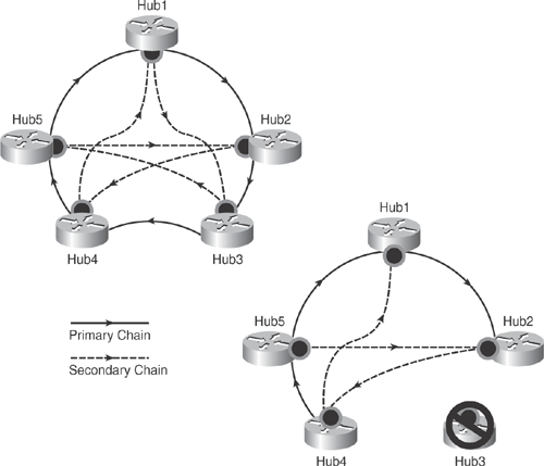
Another extension of multihub topology is to group the hub routers for large-scale, highly redundant DMVPN requirements. All hub routers can point to each other as with NHS in a daisy-chain fashion. MHSD design can be used to forward NHRP packets and data packets while dynamic spoke-spoke tunnels are being created. NHRP Resolution Request/Response always traverses the complete hub daisy chain. If any hub in the group goes down in the chain, NHRP Resolution Request/Response will dynamically converge and reroute packets to other hubs in the chain. Figure 16-10 illustrates this phenomenon.
The information concept in Figure 16-10 is taken from the Cisco Networkers session presentation# SEC-2012 – "Deploying Dynamic Multipoint VPNs (DMVPN)."

Hub routers must use the same routing protocol for both hub-to-hub and hub-to-spoke routing neighbors to exchange routing information for DMVPN networks through mGRE tunnel interfaces.
The following list shows how to configure multiple NHS on hub routers to point to each other, thereby forming a daisy-chain setup in a multihub, spoke-to-spoke, daisy-chain topology.
Single daisy chain through all hubs: Loss of hub breaks daisy chain.
ip nhrp nhs <hub<x+1>>
Two layer daisy chain: Can lose every other hub without splitting DMVPN network.
ip nhrp nhs <hub<x+1>>
ip nhrp nhs <hub<x+2>>
Three layer daisy chain: Can handle losing more hubs, but is more complex than single and two layered.
ip nhrp nhs <hub<x+2>>
ip nhrp nhs <hub<x+3>>
Figure 16-10 illustrates how the hub routers are grouped in a daisy chain and shows the primary and secondary paths. It also shows the path flow if any hub (Hub3 in this case) goes down.
As discussed previously, hierarchical (tree-based) DMVPN implementation was introduced in Phase 3 to replace Phase 2-based designs with the capability of spokes from different regions to establish dynamic and direct spoke-to-spoke tunnels bypassing central and regional hubs. In Phase 3, regional DMVPN networks are bound together to form a single hierarchical (tree-based) DMVPN network, including the central hubs. This allows spoke-to-spoke traffic from different regions to establish direct tunnels with each other, as illustrated in Figure 16-2.
Note that Phase 3 hierarchical topology is not daisy-chain topology as discussed earlier. Instead, it uses routing and CEF switching to forward data and NHRP packets optimally through hubs, thus reducing complexity. In addition, spokes are not required to learn individual private LAN routes from all the spokes (full routing table). Private LAN routes can be aggregated and summarized at the hub, thereby reducing the load for routing protocols and providing better convergence.
Caution
Phase 2 and Phase 3 DMVPN cannot coexist on the same DMVPN network. Spokes need to be migrated from Phase 2 DMVPN to Phase 3 DMVPN explicitly. Refer to the following Cisco white paper for more details on migrating from DMVPN Phase 2 to Phase 3: http://www.cisco.com/en/US/products/ps6635/products_white_paper0900.aecd8055c34e.shtml.