There are several ways to deploy CS-MARS appliance into the network. Careful planning is required before considering and selecting the appropriate CS-MARS model. The decision greatly depends on the anticipated events per second (EPS) and NetFlow flows per session (FPS) for that network or segment.
The following are two types of CS-MARS deployment scenarios:
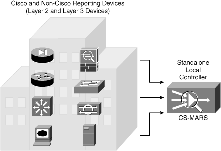
Standalone: A single CS-MARS is deployed into the network collecting raw data from one or more network devices. Standalone deployment is also referred to as Local Controller (LC).
Global: Two or more LCs are deployed into the network collecting raw data from various network devices. In this setup, a separate Global Controller (GC) CS-MARS appliance is required to manage the LC. The GC does not receive raw data from the reporting devices; it is only used to manage the LC and overall CS-MARS deployment.
There is no major difference between LC and standalone CS-MARS deployments. Both scenarios use the same hardware and software. The only difference is that standalone is an independent, fully operated CS-MARS deployment, whereas LC works in conjunction with GC and communicates primarily with the GC.
The LC performs the following functions:
Collects all raw events from various devices
Sessionizes events across different devices
Applies inspection rules for incidents
Performs false positive analysis
Delivers consolidated information in diagrams, charts, queries, reports, and notifications
Detects inactive reporting devices
Derives set of IOS/IPS Distributed Threat Mitigation (DTM) signatures based on attacks reported by monitored Cisco IPS appliances
Acts as a repository for the IOS/IPS DTM signatures, from which IOS/IPS devices can download current signature sets
Each LC model differs in its capability to process and store events from various reporting devices.
Table 23-3 shows a complete list of CS-MARS models and their capabilities (EPS and FPS) that can be deployed as local and standalone controllers.
If high availability is required in CS-MARS deployment, begin at a CS-MARS model 100 (CS-MARS-100-K9), which has RAID 1 + 0 capabilities. The models with RAID 1 + 0 have redundant power supplies and hot swappable drives. The CS-MARS models 110 (CS-MARS-110-K9) and 210 (CS-MARS-210-K9) have special built-in battery backups for RAID cache.
LCs receive and pull raw data from a wide range of reporting devices, such as routers, switches, firewalls, IDS/IPS systems, and vulnerability assessment systems.
The LC summarizes information about the health of the network based on data it receives from the reporting devices that it monitors.
Figure 23-8 depicts a standalone LC being deployed as an independent appliance and is a fully operated CS-MARS implementation.

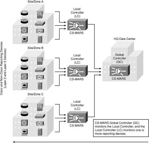
The Global Controller (GC) is used to manage two or more LC zone deployments allowing scaling of the network monitoring without increasing the management burden on the LC.
The GC provides complete control and management of the LC across various sites (zones) and provides a single user interface for defining new device types, inspection rules, reports, and queries.
GC provides a central console to manage multiple LCs. It also provides additional capabilities, including
Global authentication across all LCs
Unified report generation across all LCs
Unified rule generation for LC deployment
Global view of the network
Centralized software management
Reduced traffic across WAN links
Three basic CS-MARS models are available for GC deployment scenarios.
Table 23-4 shows a complete list of CS-MARS models and their capabilities for GC deployments.
Note
All CS-MARS GC models have redundant power capability.
Figure 23-9 depicts a GC scenario deployed at the central HQ Data Center managing several LCs across different sites.

Two major software versions are available in CS-MARS deployment. There is significant feature parity across the two releases supporting different hardware platforms. The appliance model has little impact on the available features support across the two releases.
Software Version 4.3.x: The 4.3.x software release supports the CS-MARS models MARS-20R, MARS-20, MARS-50, MARS-100e, MARS-100, MARS-200, MARS-GCM, and MARS-GC appliances.
Software Version 5.3.x: The 5.3.x software release supports features on new appliance CS-MARS models MARS-110R, MARS-110, MARS-210, MARS-GC2, and MARS-CG2R.
Note
Database table structure changes between software versions; thus, an existing database cannot be restored onto a different software version, because it can cause data corruption. If you do not require preserving any configuration and event data, it is better to start with a clean system. Reimaging it can be much faster than the upgrade procedure.
From a top-down deployment perspective (refer to Figure 23-9), CS-MARS GC monitors the LC, and the LC monitors one or more reporting devices.
A reporting device is any Layer 2 or Layer 3 device (Cisco or non-Cisco) that provides CS-MARS with raw data about the network from traffic flows and the configuration files, allowing CS-MARS to analyze and respond to possible attack targets.
A mitigation device is any reporting device that can deny a traffic flow within the attack path.
CS-MARS provides mitigation support in two forms:
For supported Layer 3 devices, CS-MARS provides recommendations for a suggested Layer 3 device for mitigation and a set of corresponding commands that can be used to stop an ongoing, detected attack. This information can also be used to manually block the attack.
For supported Layer 2 devices, CS-MARS provides recommendations for a suggested Layer 2 device for mitigation and a set of corresponding commands to stop the ongoing detected attack.
Note
Refer to Table 23-2 for a complete list of the supported reporting devices.
Based on the confirmed incident and correlated data, CS-MARS provides suggested mitigation rules for detected attacks and, in some cases, it can push those rules to the mitigation device, to stop the attack by restricting network access to the infected hosts.
Figure 23-10 illustrates an example of CS-MARS recommendation for enforcement that points along the attack path with a set of corresponding commands to stop the attack.

Another important consideration to be taken into account when deploying CS-MARS is the type of operation that CS-MARS will perform. This needs to be decided before CS-MARS is configured to receive raw data from reporting devices.
Three basic levels of operation exist in CS-MARS, based on the type of data it can collect from the reporting device. These levels dictate the capability of CS-MARS to identify attacks from end to end:
Basic: At the basic level 1, CS-MARS performs similar to a smart Syslog server, collecting logs from the reporting devices and supporting routine queries and basic reports.
Intermediate: At the intermediate level 2, CS-MARS processes isolated events and performs session-based correlation, including resolving NAT and PAT translations at the IP address layer.
Advanced: At the advanced level 3, CS-MARS functions at its full potential with all its capabilities. When advanced operation is enabled, the CS-MARS appliance discovers and displays the full topology, draws attack paths, and enables MAC address lookups of the hosts involved in an attack.
Table 23-5 summarizes the CS-MARS level of operations and the functionality enabled at each level.
Required traffic flows identify the necessary protocol and port numbers that must be allowed by gateways/firewalls/ACLs if they separate the CS-MARS appliance from a reporting device, mitigation device, or supporting device (as listed in Table 23-2). Different protocol and port numbers are used for varying functions when CS-MARS communicates with a reporting device.
Additionally, traffic flows between a GC and any monitored LCs must be allowed.
Table 23-6 identifies the various traffic flows and their associated protocol and port numbers that must be opened if there is a gateway, firewall, ACL, or any type of filtering device between CS-MARS and the reporting devices.
| Category | Protocols | Comments |
|---|---|---|
| Management GUI | HTTPS/SSL (TCP port 443) | This traffic must be enabled for GC to LC, as well as from the CS-MARS appliance to the computer used to manage the appliance. |
| Management CLI | SSH (TCP 22) | — |
| Support Servers and Services | DNS (TCP and UDP port 53)
NTP (TCP/UDP port 123) SMTP (TCP port 25) ICMP (IP level service) NFS | SMTP is used for outgoing mail services. ICMP is useful for diagnostics and troubleshooting and is required by the dynamic vulnerability scanner. NFS is used for network-attached storage (NAS) servers to retain data archives for MARS. Because NFS ports are negotiated, it is recommended that the NAS server be located on the same network segment as the MARS appliance. |
| Upgrade from GUI | HTTPS or FTP (TCP port 20 and 21) | Options from within the GUI require it. |
| Upgrade from CLI | HTTPS, HTTP (TCP port 80), or FTP | At the command line, the upgrade can be done from the DVD drive, which does not require extra opened ports. |
| Discovery of reporting device or mitigation device | Telnet (TCP port 23)
SSH FTP SNMP (TCP 161) | MARS appliance periodically contacts the devices to ensure that they are operational. |
| Monitoring of reporting device or mitigation device | HTTPS
SSH SNMP Telnet FTP PostOffice (UDP port 45000) RDEP (SSL) SDEE (SSL) syslog (UDP port 514) | |
| Policy query to Cisco Security Manager | HTTPS | Enable HTTPS access to the Common Services 3.0 server by the CS-MARS appliance. |
| Global Controller and Local Controller data synchronization | Proprietary (port 8444) | This port must remain open on the outside and inside interfaces to ensure accurate data correlation operations of the GC. |
| NetFlow | NetFlow (TCP port 2055) | Enable Spanning Trees between switches (distribution and access switch, not the core). Ports can be changed on which the appliance listens for NetFlow traffic on the Admin, NetFlow Config page. |
| Checkpoint | OPSEC-LEA (TCP port 18184)
OPSEC-CA (TCP 18210) SSLCA (TCP port 18184) OPSEC-CPMI (TCP port 18190) | Used by Checkpoint devices only. CA is used for pulling a certificate for the OPSEC application. |
| Oracle Database | Oracle Database Listener (TCP port 1521) | Used by Oracle only. |
| Microsoft SQL Server | MS SQL (TCP port 1433) | Used by FoundStone and eEye. |
| The information in Table 23-6 is compiled from "Install and Setup Guide for Cisco Security MARS, Release 5.2.x" at http://www.cisco.com/en/US/docs/security/security_management/cs-mars/5.2/installation/guide/plan.html. | ||
In addition to the listings in Table 23-6, if the GC and LC are separated by a firewall or any type of filtering device, the ports listed in Table 23-7 need to be allowed explicitly, on both the inside and outside interfaces of the firewall, to ensure proper operation of the GC.
| TCP Port | Function |
|---|---|
| 22 | Secure Shell (SSH) used by LC for topology and device discovery |
| 443 | Hypertext Transport Protocol with Secure Sockets Layer (HTTPS) used for user interface access |
| 8444 | Cisco Proprietary data synchronization between a GC and LCs |
| The information in Table 23-7 is compiled from "User Guide for Cisco Security MARS Global Controller, Release 5.2.x" at http://www.cisco.com/en/US/docs/security/security_management/cs-mars/5.2/user/guide/global_controller/gccfg.html. | |
The CS-MARS appliance can be centrally managed through a secure web-based interface supporting role-based administration.
The web-based management interface is easy to use and user friendly using a tabbed, hyperlinked, browser-based interface approach. The web-based interface can be accessed from any computer on the network that has IP reachability to the CS-MARS appliance. The web-based management interface can be used to perform all administrative functions.
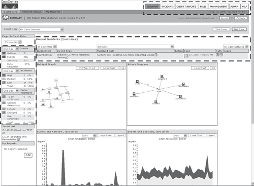
Figure 23-11 shows a sample output of CS-MARS web-based management interface dashboard (Summary page).

As shown in Figure 23-12, the web-based management interface offers seven menu option tabs in the right corner, which further allow navigating to the pages relevant to the tab's subtabs. Figure 23-12 shows sample outputs from each of the seven menu option tabs and their subtabs from the management interface dashboard.

Depending on the LC or GC, and whether you are using software version 4.3.x or version 5.3.x, several parameters need to be configured on the CS-MARS appliance system. These can either be configured via the CLI console or the web-based management interface.
After booting the CS-MARS appliance for the first time, you need to configure the following basic parameters as part of the initialization process using the CLI console. Basic parameters include the following:
Hostname
IP address and subnet mask
Default gateway addresses
DNS server IP addresses (if DNS is used)
NTP server address (if NTP is used)
Time, date, and time zone
Login via the console access to the CS-MARS system using the default administrative user account and password (pnadmin/pnadmin) to complete the basic initialization process.
After the CS-MARS appliance is initialized, all the remaining tasks, such as adding the reporting and mitigation devices, can be completed using the web-based management interface, as shown in Figure 23-12, using a standard web browser from any client PC on the network as follows:
https://CS-MARS_ip_address
Note
Prior to using the system, the device license must be installed from the web console as the first step.
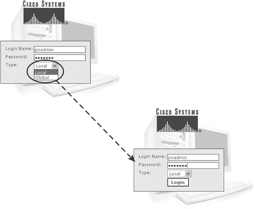
Figure 23-13 shows the default login page for the CS-MARS appliance. Indicate whether it is an LC or a GC and log in using the default administrative user account and password (pnadmin/pnadmin) or any other user account provided by the administrator.

Tip
For a comprehensive list of configurations and the user guide, refer to the following Cisco documentation pages: http://www.cisco.com/en/US/products/ps6241/products_user_guide_list.html.